POCKET TUNER V1
POCKET TUNER V1.1 UPDATE – 08/2024
I updated POCKET TUNER SCHEMATIC and PCB LAYOUT. The new layout gerber file in POCKET TUNER github page: https://github.com/WB2CBA/POCKET-TUNER-V1
The reason for this update was a difference in using the rotary encoders. Although I posted a linear increment Excell sheet for capacitor selection my method was a random selection. I chose this to get to the capacitor value faster than going through all capacitance values. It is like hit and miss. This created a confusion with fellow hams who built this tuner. I came to the conclusion that linear increment is a more intuitive method to get used with.
Also lowering 51 ohm / 2W resistors to 47 ohm 2 W resistors gave a better correlation between tune and actual SWR values.
Anyone who is just ordering the pcb will be covered by these changes if they download the gerber file from github page. They don’t need to make those changes listed below,
For users that are already built this pocket tuner here are changes listed to upgrade to this new scheme:
- Replace R1 -R2-R4 51 ohm/2Watt resistors with 47 ohm 2 Watt resistors.
- Swap C4 and C5 capacitors.
- Swap C8 and C9 capacitors.
- Swap C10 and C11 capacitors.
- Swap C14 and C15 capacitors.
The value of those capacitors are same. We are just changing the location of those capacitors by swapping them with each other.
Now you will have a easier tuning experience with POCKET TUNER.
A Credit Card sized HF T-MATCH ANTENNA TUNER for QRPp and QRP Portable Operations
Lately I am fascinated with miniscule RF power HF rigs and their performance on Digital Modes such as FT-8 and FT4.
Almost a year now I work QRPp on HF Digital Modes with a highly portable QRPp HF Transceiver with Sub 500 mW RF output from Parks, backpack hikes and from my car. I work mostly on 10m to 17m with my rig. All my QRPp QSOs can be checked on my QRZ log performed with my tiny rig.
All working great except with one minor issue, lacking a highly portable antenna Tuner to accompany my setup in my backpack. ATU type tuners such as ATU-10 or so fail to tune below 500 mW!
My go to Tuner is a 4State QRP tuner which I grabbed from a hamfest as a second hand. This tuner designed by David Cripe, NM0S and works like a charm! The only issue I have is it’s size!
I wanted something the size of a credit card as a Tuner! So I took this challenge upon me and designed a T-Match tuner similar to David Cripe’s excellent 4State QRP Tuner with a twist and way smaller than that.
Before miniaturization process of David Cripe’s Tuner I contacted David Cripe to have his blessing on copying his design especially of his excellent SWR led tuning indicator. David was kind enough to grant his approval of using his tuning indicator design. I can’t thank him enough for his kind gesture. Thank you David!
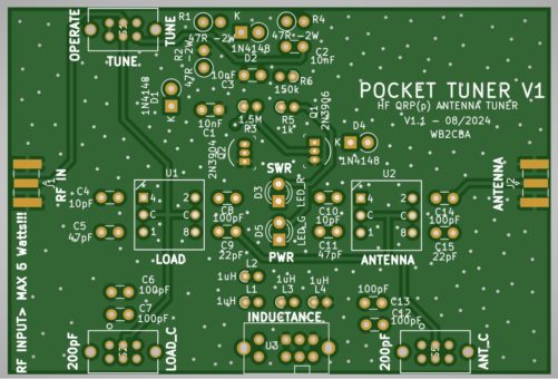
So this is what I came up with sitting side by side with my credit card.
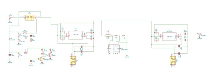
Here is schematic of POCKET TUNER V1:
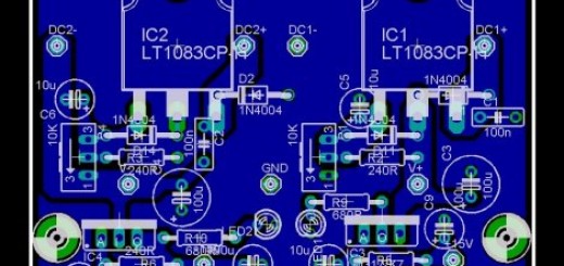
And here is PCB LAYOUT:
After this photo debut let’s talk about how this little thing works and how to build one!
Some specs and aspects of this pocket tuner:
- Works on HF Bands from 10m to 40m. Struggles on 80m in this current configuration of inductance though it can be set to work on lower end bands by playing with inductance values. I will get to that below.
- I can tune up to 5 watts with this tuner though my aim was more in QRPp zone which is sub 1 watt! Though I successfully used it with my ADX,QDX and QMX without any issues by keeping tuning TX times under 10 seconds at a time not to heat up excessively. Then it works like a champ! :)
- It has a resistive tuning process indicator which is similar to any resistive tuner meaning does not stress your TRX in tuning mode by lowering SWR in tuning to 2 or lower. This is great not to expose RF PA output stage to excessive SWR conditions while tuning as this is the case in Automatic Antenna Tuners.
Let’s talk a bit about limitations of this tiny tuner:
- Aimed for Sub 1 Watt operation though can be used up to 5 watts by being considerate on Tune TX times.
- DISCLIAMER: DO NOT attempt to use it over 5 WATTS! Certainly not on 10 WATTS!
How this tiny tuner works:
The tuner part of this tuner is a classic T-Match antenna tuner consisting of two series capacitor banks and a switchable inductance bank between two capacitance banks and ground potential.
Nothing special here, those parts that are unique to this antenna tuner is how those capacitance are switched and the inductances used.
Let’s start with the capacitance banks labeled as Load and Antenna capacitance. In a classic T-match portable tuner like 4State QRP tuner poly-varicon variable capacitors are used.
In my pocket tuner design I was seeking a different method for the sake of compactness as poly-varicon caps are not as small in size to fit in a credit card footprint.
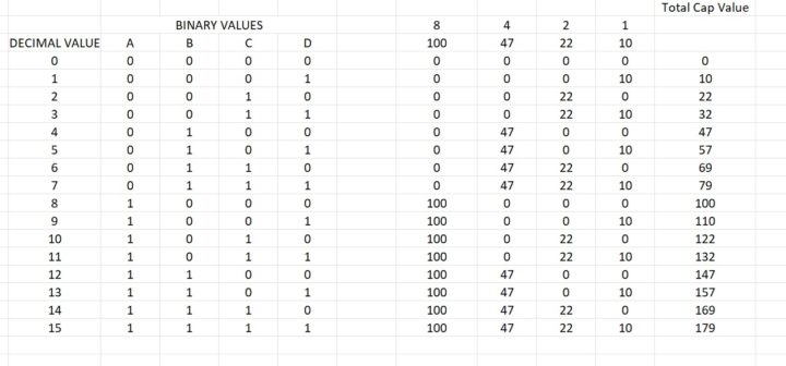
Here is my method to walk around that variable capacitor footprint size problem. I used hexadecimal rotary switches which can switch 4 input to one common output pin in Hexadecimal 16 possible combinations as outlined in the table above. We have 16 positions coinciding with 16 – 4 bit combinations. If we connect 10pf to LSB digit pin and 22pf following that and 47pf to the next pin and 100 pf to MSB pin then we can switch between 10pf to 179 pf
close to 10pf increments.
Now if we add another 200pf in parallel to this HEX switch capacitor bank with another switch now we can go up to 210pf to 379pf. This will give us a range of 10pf to 379pf in approximate 10pf increments.
Those HEX rotary switches are much smaller in size when compared to poly-varicon caps in footprint. On Inductance side I used 1uH axial fixed inductors. Inductance slide switch is a 3 position switch, in position one I used two 1uH inductors parallel to create a 0.5uH inductance. On position two another 1uH inductance is added to 0.5uH and total inductance becomes 1.5uH.
On third switch position another 1uH is added to 1.5uH to have a total inductance value of 2.5uH.
From 10m to 17m inductance switch position one which is 0.5uH generally favors a good tune. For 20m and 30m second inductance switch position favors much better. For 40m generally with my antennas inductance switch position three works better.
This is my observation with my antennas. This might vary for different antenna types and conditions.
2.5 uH total inductance is not favorable for 60m or 80m antennas. To use this tuner for 60m or 80m bands I suggest to increase last switch position inductor to 2uH by connecting another 1uH inductor series to the existing L4 – 1uH one. I haven’t tried this but theoretically it should work. For tuning indicator as I mentioned above I used David Cripe, NM0S’s design used on 4State QRP Tuner. What I like in this design is that we have two LED indicators, Red and Green. Red is for SWR and Green is for forward output. The aim in tuning is to have Red LED as dim as possible and Green led as bright as possible. When both Green and Red LEDs are bright SWR will be less than 2! This is a great indicator, very intuitive to use.
Building POCKET TUNER V1:
I posted all relevant data, gerber file for Printed Circuit Board and including this write up and photos in my github page under this address:
https://github.com/WB2CBA/POCKET-TUNER-V1
First step is to download and order POCKET TUNER V1 PCB from one of those PCB fabrication houses. Here are links to couple of them:
www.jlcpcb.com
www.pcbway.com
Anyone of these Chinese PCB vendors can fabricate POCKET TUNER V1.
Except HEX Switches and slide switches all other parts are non-critical and can be outsourced from any online vendor. Though I used some SMD caps and resistors for my version, all parts are through hole parts. I used smd parts as I didn’t have through hole parts in my stock. Also smd caps and resistors can be used as an alternative as footprint spacing is adjusted for 0805 footprint.
I uploaded a detailed BOM list file for parts with links to buy those switches from.
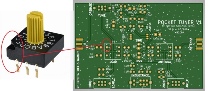
When soldering HEX Rotary switches SD-1110, match skew angled notch on the switch with the skew notch line on the pcb.
Here is a photo of of that skew notch:
There is no case or cover for this tuner. A 3D case would be nice. Though it is so tiny and simple I didn’t need a case to cover it.
Those SD1110 shafts are knurled and not easy on fingers. My friend Ken Delap, KX9U came with a brilliant solution to this problem! He cut two 1/4”(7mm) length pieces from a 1/8”(3.5mm)fuel line hose and used those as knobs! Works perfect! These makeshift knobs can
be seen on my version photo above.
Here is a link of that fuel line hose on amazon to give an idea:
How to use POCKET TUNER V1:
Using this antenna tuner is similar to using any manual T-match antenna Tuner.
To start tuning:
- Tune switch should be set TUNE.
- Connect ANTENNA end to an Antenna and connect RF IN side to your Transceiver.
- Leave LOAD_C and ANT_C switches in opposite side of 200pF mark where LOAD_C and ANT_C is written. This means initially we are not adding 200pF to existing capacitance.
- – Now transmit and play with INDUCTANCE selector switch to observe a dim in RED LED and/or brightening in GREEN LED. If there is dimming then leave inductor switch at that position.
- Now advance LOAD Rotary switch clockwise and observe if RED LED dims and GREEN LED gets brighter. Leave the position where you get brightest green and dimmer red LED.
- Now it’s time to rotate ANTENNA rotary switch while observing if RED led is dimming further and/or Green LED is getting brighter.
- You can also add 200pF capacitance and try both switches again to get dimmer RED LED and brighter GREEN LED.
- The aim of tuning is to get RED LED as dim as possible and get GREEN LED as bright as possible while trying different combinations of both LOAD and ANTENNA capacitance rotary switches and trying to add extra capacitance of 200pF to both LOAD and ANTENNA if needed.
- When tuning is satisfactory stop TX and push TUNE switch from Tune to Operate. Now tuner is in operate mod and can TX full power of TRX.
This tuning process is a fine dance of trial and error while playing with different combinations of switches to achieve a dimmer RED LED and brighter GREEN LED. This is the process always in similar T-Match antenna tuners. Patience is a virtue in this process! When Tuning is on Transmit power is lowered with a resistive load and TRX sees a max SWR = 2 so that PA RF stage won’t be stressed with high SWR and safe.
Tuning with high powers close to 5 watts it is a good idea to stop TX every 10 to 15 seconds to avoid stressing the Tuner with excess heating.
Tuning with high powers close to 5 watts it is a good idea to stop TX every 10 to 15 seconds to avoid stressing Tuner with excess heating.
Tuning tests with POCKET TUNER V1:
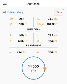
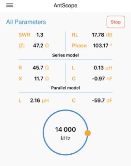
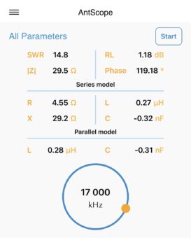
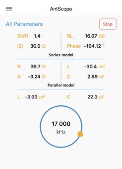
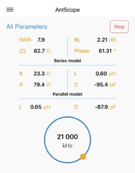
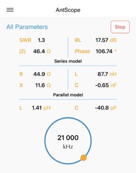
I have a 10m MFJ Vertical Antenna which I use in my car setup. This is a 10m/28 Mhz tuned antenna. I carried out a verification test of this tiny tuner to see if it can tune my 10m antenna on different bands .
I have a Rigexpert A55 Zoom antenna analyzer. I connected this analyzer to ANTSCOPE app which is RIGEXPERTS official phone app where you can view all your antenna values conveniently.
I setup POCKET TUNER between my 10m antenna and Rigexpert Antenna analyzer.
Here are some screenshots of BEFORE tuning and AFTER tuning values of 14Mhz, 17mhz and 21 Mhz frequencies. This tiny tuner can tune a 10m vertical antenna on these frequencies like a champ! :)
This POCKET TUNER V1 made my life easier as it doesn’t occupy much space and simple to use with enough patience in my backpacking and travel adventures.
I hope others also will build and use it.
Please let me know about your user experience and comments are welcome.
Enjoy!
Barb WB2CBA – 05/2024
wb2cba@gmail.com


