FRANKENMETER – A Simple QRP POWER/SWR METER
A Simple QRP POWER/SWR METER
For some time I am experimenting with designing a simple QRP automatic antenna tuner to pack into my uSDX TriBand rig. When searching web I came across David Fainitski, N7DDC, ATU-100 design.
Here is N7DDC ATU-100 Github page for your reference:
https://github.com/Dfinitski/N7DDC-ATU-100-mini-and-extended-boards
N7DDC ATU-100 is an excellent and relatively cheap ATU design which became instantly very popular among ham community. You can find this ATU in almost every online electronic store.
Before going any further I would like to acknowledge and thank David Fainitski, N7DDC for his great work on this ATU-100 Automatic Antenna Tuner and posting it open source and public.
Ok long story short as a modest PIC programmer my aim is to adapt his code to my needs so I wanted to explore how his tandem match and related PIC micro code is working. To achieve this I isolated ATU 100 tandem match circuit and pic micro and put together this quick and dirty test pcb! And surprisingly it worked pretty good! After experimenting with it sometime I started to carry it with me for my sota quests to check my portable antenna condition meaning RF power vs SWR values. It turned out to be a good companion gadget. It draws only 10 milliamps so it can be powered with a 9 volt battery and lasts long enough. A ham friend of mine christened it as Frankenmeter hinting Frankenstein due to it’s extraction from ATU-100 circuit!
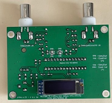
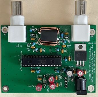
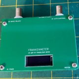
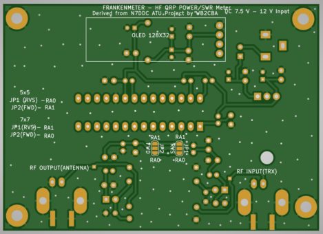
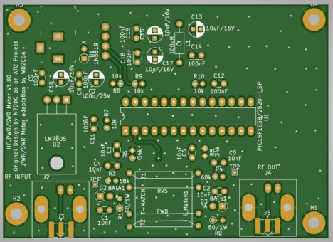
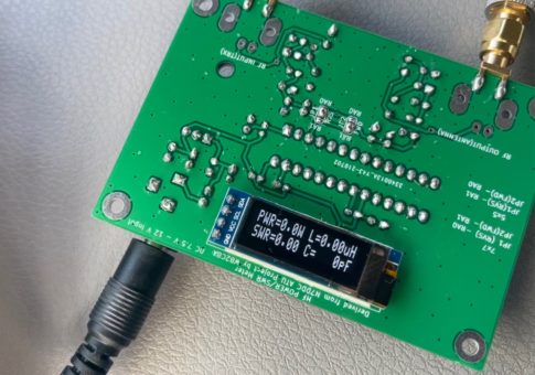
So here is how FRANKENMETER looks like:
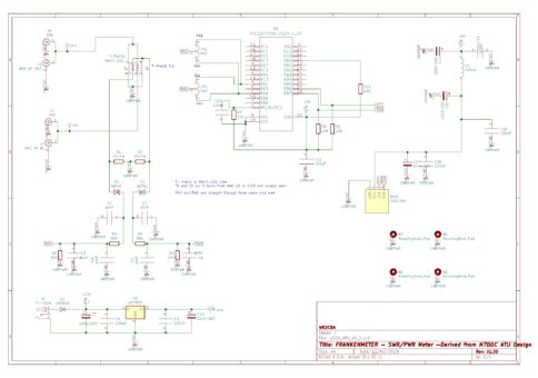
This is the Schematic of Frankenmeter:

It is easy to build simple circuit. We have a tandem match consisting of two 5 turn coil in each side of BN43-202 binocular core. A reverse and Forward line is passing rf signal to output and measures power and return loss as SWR. AWG 24 or 0.5 mm copper enamel wire is good enough for qrp power rating measurements. I tested this power/swr meter up to 10 watts. I am sure it can go beyond that but I haven’t tested so exercise with caution!
For display I used 128×32 OLED as it is small enough and easy to find in the market.
I modified PIC micro firmware to work with this configuration meaning QRP power, 128×32 OLED and 1:5 Tandem match.
PIC micro can be programmed with pickit 3 programmer which can be found on ebay, amazon or Alibaba less than 20 US$.
Here is a link for pickit 3 programmer:
https://www.ebay.com/itm/253598278171?chn=ps&mkevt=1&mkcid=28
I didn’t include an ICSP programming connector in this pcb design due to display wiring using the same ICSP pins of picmicro. I used PIC16F1938 DIP version and modified firmware for this picmicro so I suggest using PIC16F1938.
I would suggest to buy with a zif programming socket as this makes life easier when it comes to programming as there is no ICSP.
Here is the link for Pickit 3 software:
http://ww1.microchip.com/downloads/en/DeviceDoc/PICkit3%20Programmer%20Application%20v3.10.zip
Using pickit 3 is relatively easy though it might create a challenge in some Windows 10 PCs. It is easier and hassle free in an old windows OS such as Win 8 or Win 7.
Steps for programming are:
1- Install pickit 3 software
2- Connect Pickit 3 to USB of PC and plug in PIC16F1938
3- Choose PIC16F1938 from device drop down menu of pickit 3 software and select.
4- Press blank button to check if PIC16F1938 is blank if not press erase then check blank.
5- Go to File/import and choose frankenmeter.hex file which is in Frankenmeter_update_07262021.zip file with the rest of the useful files for this project.
6- Press WRITE button and wait until green “programming successful” banner appears and we are done.
7- Swap the programmed PIC16F1938 into it’s DIP socket on Frankenmeter.
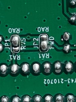
There are two jumpers on the solder side of the board named as FWD and RVS. These are added for my test purposes. For this pwr/swr meter application please solder jumper settings as in the photo below:
Using Frankenmeter:
Using Frankenmeter is as easy as using any other Power/SWR meter. RF input is connected to Transceiver antenna output and RF output is connected to antenna. When we power up classic ATU-100 splash screen greets us with N7DDC callsign and “ATU-100 mini V3.2” appears. I didn’t touch or remove or change this splash screen on purpose for two reasons: To honor and give credit to N7DDC’s work on ATU-100 tuner project. And not to copy or claim his work inadvertently as mine which is not!
Then we see the classic idle screen of ATU-100 as if it is an ATU-100! Thinks that it is still an ATU! Identity crisis! :)
When we transmit the display screen shows four values:
– RF Power input from TRX
– actual RF power output to antenna
– SWR
– Actual RF output Efficiency in %.
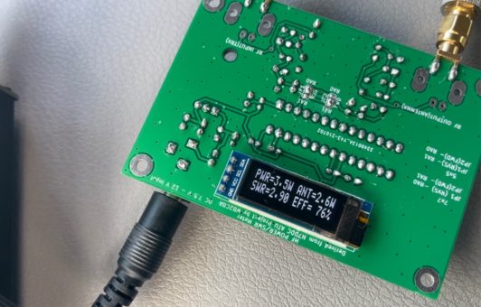
As an example of a bad SWR and antenna condition:
RF power input is: 3.5 Watts
SWR is 2.90 which is not ideal so we are observing rf loss due to returning rf power.
Actual RF power that goes out to antenna is 2.6 watts and power input to power output efficiency is 76%.
This test is under 50 ohm load conditions which is ideal SWR condition.
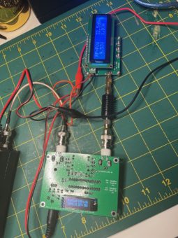
As can be observed RF input versus output power is almost the same and is 1.01 SWR. Minute loss of power. Efficiency is 99%. Also we can observe that RF power measurement of both RF powermeter and frankenmeter is almost same which is good news on accuracy and efficiency of Tandem Match.
So Why it is 1.01 SWR but not 1.00 SWR as Dummy load, in this case rf attenuator is matched to 50 ohms? It is because I used 49.9 ohm resistors in Frankenmeter as I didn’t have exact 1% tolerance 50.0 ohm ones! Does it matter? I don’t think so. The difference is negligible.
So this is Frankenmeter as my friend John calls it! Born from the ashes of infamous ATU-100 Tuner of N7DDC and my quick and dirty test pcb approach! I hope QRP Enthusiasts will embrace it as a useful tool in their QSO quests!
Barbaros Asuroglu aka Barb, WB2CBA
NY, U.S.A. 07/2021

