Octoband uSDX
OCTOBAND – 8 Band PA+LPF Board For uSDX TriBand (An All Mode HF QRP Transceiver)
It’s been sometime since I designed uSDX TriBand – A three band all mode SDR HF QRP Transceiver based on Guido, PE1NNZ’s brilliant Arduino firmware.
Here is the link for uSDX TriBand design article:
https://antrak.org.tr/blog/usdx-triband-sdr-all-mode-qrp-transceiver/
Band selection in uSDX TriBand is mainly by two 3 pole slide switches. This method was chosen to keep things simple with KISS(Keep It Simple Stupid) philosophy. Time showed that keeping things simple is not always the best approach! This band selection method wasn’t fool proof meaning that if one of the switches left in a position other than selected band then there was a possibility of smoking PA mosfets! Not good!
So for sometime I was sitting on an idea of designing an 8 band Power amplifier and Low pass filter module with auto band select relays without any worry to smoke those Power Amplifier mosfets!
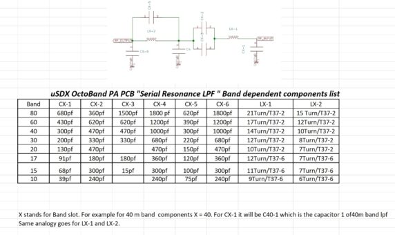
What was holding me, mostly crazy schedule of my day job and the burden of configuring and setup 8 bands in a board layout without sacrificing too much of that efficiency and RF Output Power! This meant tweaking pcb layout and tracks as well as caps and toroids for stray capacitance between tracks. Oh boy as an RF infant I never thought this can be that hard and it was hard! – LPF design on uSDX OctoBand is Manuel Klaerig, DL2MAN’s efficient serial resonance filter and 8 band multiband solution which can efficiently deliver 3.5 to 5 watts depending on band. Thank you Manuel for this great multiband lpf design. My special thanks goes to Ken Delap, KX9U for calculating and devising a graphical approach for capacitors and toroid windings for each band used in this design.
OCTOBAND 2.0:
So what happened to V1.0? Short story it didn’t work! PA was putting out 4 watts and all bands came out milliwatts to antenna output! So here is the long story, as you know by now my motto is through hole component designs everyone can solder with a soldering iron only!
So in V1.0 – 8 bander design I chose through hole components and one relay for each band. Bad idea! The tracks were all over the place to reach all components and relays. This wreaked havoc on RF as stray capacitance and interference was eating out all RF power output. Ken and I scratched heads for sometime. To overcome this problem we needed to use a 4 layer pcb and smd components! This will refine tracks driving relays vs power vs ground plane issue by dividing those into each of those 4 layers. Also smd components will sort the rf through hole problem meaning that it will prevent RF route going through hole vias which creates RF loss.
4 layer pcb! smd components! So much for my KISS(Keep It Simple Stupid)approach! No way Jose!
So here are details of the compromise 8 bander which works reasonably good with through hole parts in V2.0:
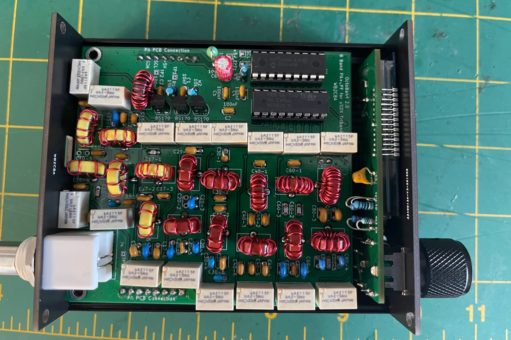
Here is the finished and installed OCTOBAND 2.0 pcb in Usdx TriBand.
The design compromise to get all working in a double layer through hole pcb was to use two relays for each band. By doing so LPF RF line kept pretty straight inline with the rf input and antenna path reducing unnecessary track layout maneuvers and though hole Via problems. I managed to keep all rf tracks on solder side of the pcb which helped a lot to reduce rf track layout loss.
RF loss was one side of the design problem! Now we had a digital problem in our hands also! As the aim was to use all through hole components using DL2MAN Rev3 lpf define in firmware was not an option with smd TCA9555 i2C port expander. So the next best option was to use a through hole I2C to I/O Expander.
MCP23008 is an I2C 8 bit port expander which can be purchased in Through hole format and readily available online.
I chose to use small footprint signal relays from KEMET to fit 16 relays on the pcb which can be obtained from many online electronic part stores. I’ll give the link and details later. These relays tax 20mA each and they are non latching. So MCP23008 needs to drive 2×20 mA = 40 mA which is beyond it’s capability. So I decided to use ULN2803A 8 bit darlington driver for relay driving which can sink up to 500 mA. ULN2803A also has reverse protection diodes built in for each relay which saves parts.
Then came the need for a new define in uSDX firmware to drive these relays for each band in sync. Big thank you goes to Guido, PE1NNZ and his patience with me going through endless testing to get this new define code on firmware to work on this new band driving scheme. If it wasn’t Guido’s brilliant ideas and coding on this I could’ve never release this board. Thank you Guido for everything!
So what are the pros and cons of this 8 band selection scheme. Well it works and now we have 8 bands on triband selected automatically when we change bands over the menu. The con is RX milliamp is now taxing 110 mA due to 2 relays on per band all the time. Is it a big deal? I don’t think so in today’s LI-Ion battery technology. The other disadvantage may be the cost of buying 16 relays instead of 8 but is it? 4 layer pcb and smd components? I am leaving that comparison and judgement to you.
So enough for the story part let’s get real!
Building Usdx Triband OCTOBAND 8 Band PA+LPF BOARD:
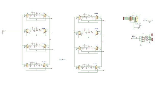
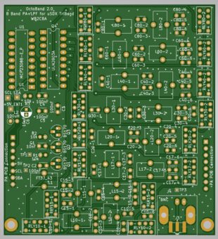
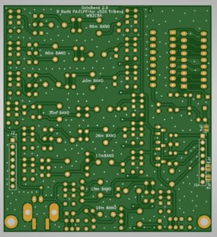
Here is the link for Usdx octoband Gerber Files, schematic, pcb layouts and band dependent components excel sheet. OCTOBAND PA_LPF.zip
This table outlines each capacitor and toroid type and winding detail for each band. OCTOBAND supports 80m, 60m, 40m, 30m, 20m, 17m, 15m and 10m bands.
– For relays I used KEMET UA2-5NU small signal relays mainly for their tiny footprint and enough amps they can hold on.
– Here is a link from Digikey for these relays: https://www.digikey.com/en/products/detail/kemet/UA2-5NU/5502071
– Mouser link: https://www.mouser.com/ProductDetail/KEMET/UA2-5NU?qs=Mg2Do3ryY8thjS4jUuWNRA%3D%3D
– MCP23008 is Microchip manufactured I2C 8 bit port expander. Here is digikey link for MC23008:
Here is digikey link for it:
https://www.digikey.com/en/products/detail/microchip-technology/MCP23008-E-P/735951
– ULN20803A is a common 8 bit darlington driver IC.
– ULN2803A Digikey link: https://www.digikey.com/en/products/detail/stmicroelectronics/ULN2803A/599591
The rest of the parts are readily available capacitors, resistors, BS170s etc. Try to use 100V caps for all band lpf capacitors.
OCTOBAND, 8 band pcb can be adapted to any uSDX Triband build out in the wild. I will give an example how to adapt a COG LCD Display version of uSDX TriBand. The other display option adaptations are similar.
Here are couple of steps to prepare the main board of uSDX TriBand for OCTOBAND PA+LPF board installation:
1- LCD contrast potentiometer modification:
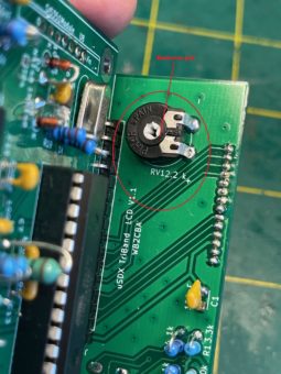
As this 8 band pcb footprint is same as main board pcb, octoband pcb interferes with the LCD contrast potentiometer.
– First step is to remove that potentiometer.
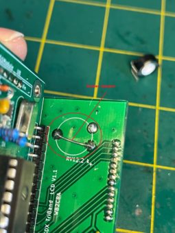
– And then solder a jumper wire as shown in the photo below.
Capacitors on your belly! :
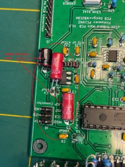
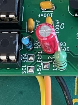
There are 3 electrolytic capacitors that might interfere with octoband pcb when it is stacked on top of main pcb. These caps needs to lay flat on their belly to get out of the way. See photo below:
Now we need to connect the +5V, GND, SDA and SCL lines of the OCTOBAND Pcb to Main PCB:
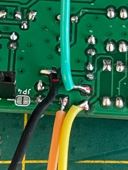
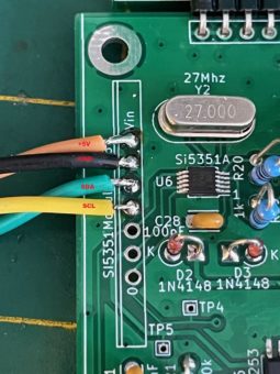
These photos show 4 electrical connections that needs to be connected with short piece of insulated wires between Main board and OCTOBAND pcbs. On OCTOBAND you will see 3 pads named as +5V, SDA and SCL. Ground can be any ground point close to these pins. I soldered these connection cables on solder side of OCTOBAND pcb to keep the length of wires as short as possible.
These pads will be carried out with 4 short wires to SI5351 module pins as shown in the photos. Try to keep the wires as short as possible. 2” (50 mm) wire length should be good enough for connection length.
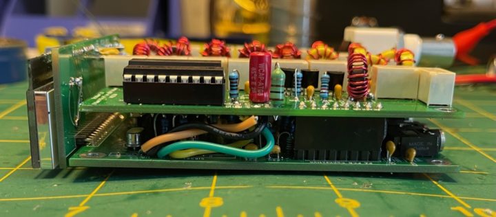
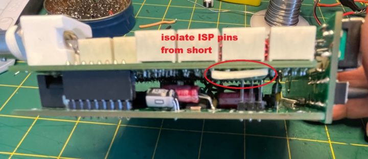
After soldering all 4 connections mate the OCTOBAND pcb with main pcb as shown in the photo. Check in between two pcb for any components that might touch octoband pcb solder side. If that’s the case isolate with an electrical tape or bend the component to get out of the way on main board. Also watch out if ISP pins are close to or shorting OCTOBAND pcb solder layer.if that’s the case again isolate with electrical tape.
– Tuck in excess connection cabling between two boards to get them out of the way.
For testing and adjustment of OCTOBAND PA+LPF pcb please refer to uSDX TriBand PA+LPF section. It’s not different than original PA adjustment.
FIRMWARE:
For OCTOBAND to be active and usable uSDX firmware version V1.02t or above should be used. Any other version won’t work with OCTOBAND PA+LPF band board as there is no band select provision on older versions suitable for this board.
You can download V1.02t firmware from this link:
https://github.com/threeme3/QCX-SSB/blob/feature-rx-improved/QCX-SSB.ino
To activate OCTOBAND board just uncomment this define: (Uncomment means remove // )
#define LPF_SWITCHING_WB2CBA_USDX_OCTOBAND 1 // Enable 8-band filter bank switching: non-latching relays wired to a MCP23008 GPIO extender on the PC4/PC5 I2C bus; relays are using GND as common (ground), GP0..7 used by the individual latches K1-8 switching respectively LPFs for 80m, 60m, 40m, 30m, 20m, 17m, 15m, 10m
The rest of the defines depends on what configuration your uSDX TriBand rig is build, meaning LCD or OLED, 25 mhz SI5351 Module or SI5351 smd chip with 27mhz crystal.. Those selection of defines should be uncommented to match the uSDX TriBand build configuration and has nothing to do with OCTOBAND define. Please refer uSDX TriBand design build article for details.
What are those 3 jumpers at the solder side of the pcb?
JP2, JP3 and JP4 is to connect pin header pins to SDA, SCL and +5V lines of OCTOBAND. This is a provision if any fellow ham designs their own uSDX main pcb and decides to use this octoband pcb in their design as their band switching board. These jumpers gives them a clean straight through connection via header pins without messing with cable connection.
These jumpers are not to be used in existing uSDX TriBand design! IF YOU ARE USING ORIGINAL uSDX TriBand main board to use with this OCTOBAND pcb then DO NOT SOLDER JP2, JP3 and JP4! It will just short everything if you do so!
So is this thing really working?
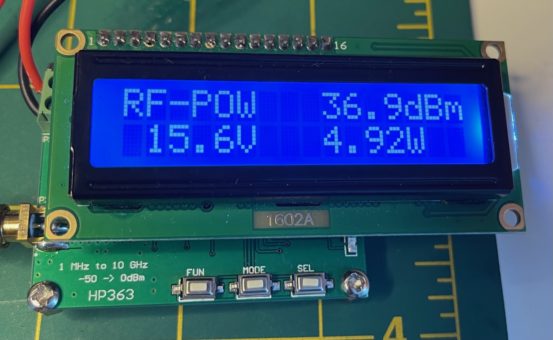
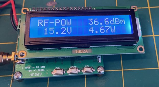
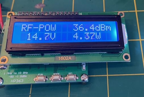
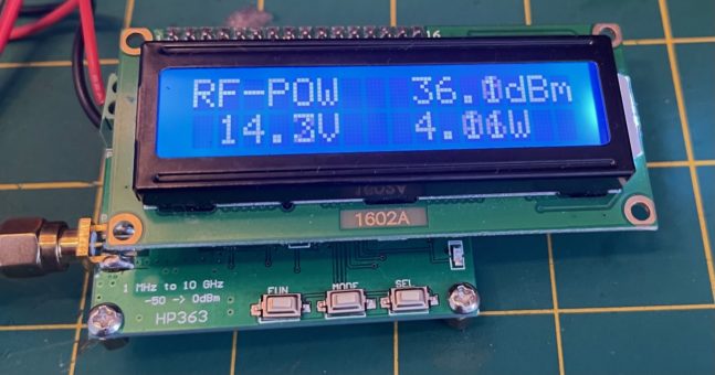
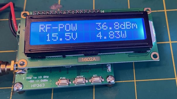
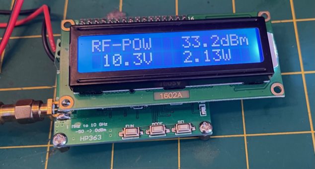
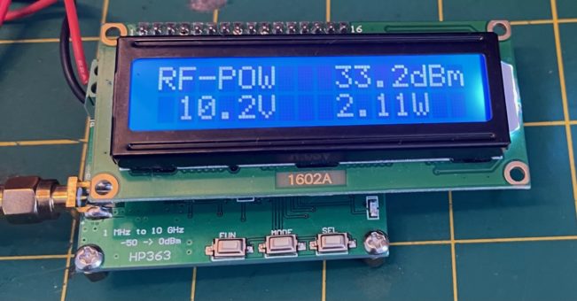
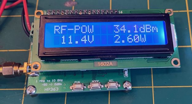
Here are some RF power output measurements:
80m Band:
60m band:
40m Band:
30m Band:
20m Band:
17m Band:
15m Band:
10m Band:
Are these RF power outputs good enough? It is ok for my needs. Do we have more room to improve? Yes certainly we have especially on 17m, 15m, and 10m bands. With these LPF component values overall efficiency is around 70 % and can certainly be improved by playing with lpf capacitor and toroid winding values for each band. Wish I had the time and patience with enough OCD factor in me to achieve this! I am leaving improving efficiency to the ham community.
I’ll love to hear your improved efficiency value components of lpfs to update this article.
I hope ham community will find useful this OCTOBAND 8 band auto switch PA+LPF to upgrade their uSDX TriBand. It certainly adds a different perspective and user pleasure to uSDX TriBand. Now PA Mosfets are feeling much safer! :)
73,
Barbaros (Barb) Asuroglu, WB2CBA
NY, U.S.A July 2021
wb2cba@gmail.com

