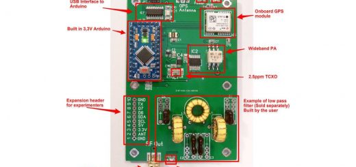
QuadBand – 4 Band PA+LPF Board For uSDX TriBand (An All Mode HF QRP Transceiver)
QuadBand – 4 Band PA+LPF Board For uSDX TriBand (An All Mode HF QRP Transceiver)
It’s been sometime since I designed uSDX TriBand – A three band all mode SDR HF QRP Transceiver based on Guido, PE1NNZ’s brilliant Arduino firmware.
Here is the link for uSDX TriBand design article:
https://antrak.org.tr/blog/usdx-triband-sdr-all-mode-qrp-transceiver/
Band selection in uSDX TriBand is mainly by two 3 pole slide switches. This method was chosen to keep things simple with KISS(Keep It Simple Stupid) philosophy. Time showed that keeping things simple is not always the best approach! This band selection method wasn’t fool proof meaning that if one of the switches left in a position other than selected band then there was a possibility of smoking PA mosfets! Not good!
So for sometime I was sitting on an idea of designing an 8 band Power amplifier and Low pass filter module with auto band select relays without any worry to smoke those Power Amplifier mosfets!
I designed and released 8 Band relay switched PA+LPF board for uSDX Triband TRX. Here is the link for OCTOBAND – An 8 Band uSDX TriBand PA+LPF Combo.
https://antrak.org.tr/blog/projeler/octoband-usdx/
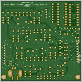
QuadBand 1.0:
Actually I designed this QuadBand board before the OctoBand to test relay switching method and efficiency of two relays in one linear LPF chain. After testing it and being convinced that it works I switched to design OctoBand which is released for fellow hams experimenting couple of months ago.
Then I thought may be it will be a good idea to release this QuadBand design too as not everyone wants to build a full 8 band version of PA+LPF for triband. To be honest for a tiny portable rig for SOTA it is more practical to have 4 bands, at least works for me. It’s a personal preference I think.
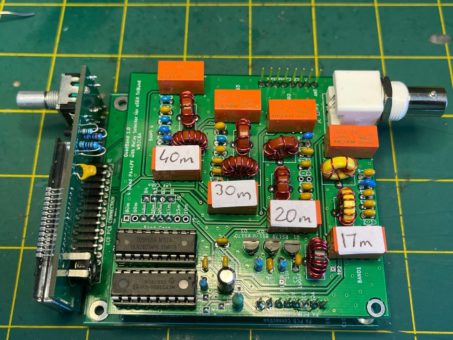
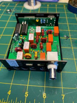
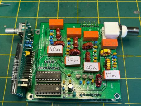
Here is the finished and installed QuadBand 1.0 pcb with uSDX TriBand.
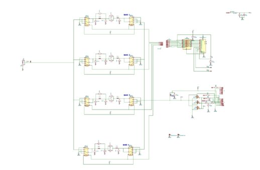
Relay drive and LPF in QuadBand are same as OCTOBAND PA+LPF Board. For details of relay switching technique please refer to OCTOBAND PA+LPF Article.
https://antrak.org.tr/blog/projeler/octoband-usdx/
I chose to use small footprint 5V signal relays from KEMET EC2_5NU to fit 8 relays on the pcb which can be obtained from many online electronic part stores and from Aliexpress. I’ll give the links and details later. These are relatively cheaper relays than OCTOBAND relays.
Building Usdx Triband QUADBAND 4 Band PA+LPF BOARD:
Here is the link for Usdx quadband Gerber Files, schematic, pcb layouts and band dependent components excel sheet. QuadBand_PA_LPF.zip
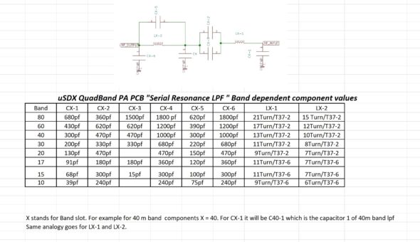
This table outlines each capacitor and toroid type and winding detail for each band. QuadBand supports 80m, 60m, 40m, 30m, 20m, 17m, 15m and 10m bands. So you can choose any 4 bands you have decided to use on QuadBand from above table and mix and match on the board for each LPF band slot.
– For relays I used KEMET EC2-5NU small signal relays mainly for their tiny footprint and enough amps they can hold on.
– Here is a link from Digikey for these relays:
https://www.digikey.com/en/products/detail/kemet/EC2-5NU/4291118
– Mouser link:
https://www.mouser.com/ProductDetail/KEMET/EC2-5NU?qs=iaWy59%2Fd4KBsEXrvQOQZ4w%3D%3D
– Aliexpress link
https://www.aliexpress.com/item/4000154756172.html
– MCP23008 is Microchip manufactured I2C 8 bit port expander. Here is digikey link for MC23008:
Here is digikey link for it:
https://www.digikey.com/en/products/detail/microchip-technology/MCP23008-E-P/735951
– ULN20803A is a common 8 bit darlington driver IC.
– ULN2803A Digikey link: https://www.digikey.com/en/products/detail/stmicroelectronics/ULN2803A/599591
The rest of the parts are readily available capacitors, resistors, BS170s etc. Try to use 100V caps for all band lpf capacitors.
QUADBAND, 4 band pcb can be adapted to any uSDX Triband build out in the wild. I will give an example how to adapt a COG LCD Display version of uSDX TriBand. The other display option adaptations are similar.
Here are couple of steps to prepare the main board of uSDX TriBand for QUADBAND PA+LPF board installation:
Selecting Relay Band Connections:
QuadBand has 4 band LPF filters and there are 8 band choices we can use on these LPF banks so how we make sure right band is selected when we select that band! Here we go:
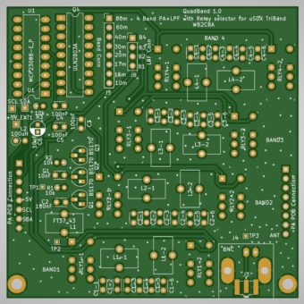
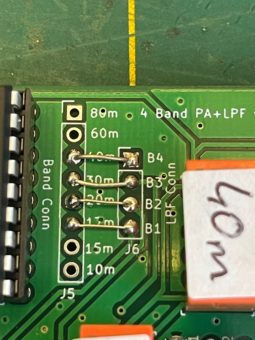
There are two rows of connection headers on Quadband pcb, these are called Band Conn and LPF Conn. Band conn has 8 pin holes corresponding to 8 bands from 80m to 10m. LPF conn has 4 pin holes corresponding to each band LPF bank on quadband pcb labeled as B1,B2,B3 and B4 corresponding to 4 LPF band banks.
So for example let’s take my band choice. I chose to build 40m, 30m, 20m and 17m bands in my quadband as in the photo below.
Band 4 which is the farthest band from BNC Antenna connector is 40m band. Band3 lpf bank which is 30m band and then band 2 lpf bank holds 20m band and the closest band lpf bank to BNC antenna connector is Band 1. It is always a good idea to mark your bands on the relays as I did.
Now we need to connect those lpf band banks to coinciding band select pins of MCP23008 as in the photo below using those LPF conn and Band Conn pins.
So 40m band pin is connected with a short wire to B4 of LPF conn pin. 30m band is connected to B3 LPF Conn pin.20m is connected to B2 lpf conn pin and lastly 10m band pin is connected to B1 which is LPF Bank 1 as in the above photo. Now when we select each installed band from uSDX Triband and all relative band relays will be active, synchronized with our band selection.
IMPORTANT TIP: When selecting which band to install in which LPF bank it is a good practice to install the higher frequency band in the closest LPF bank to BNC antenna connector. In my example 17 m is my highest frequency in my band choice which is 18 Mhz so I installed 17m on LPF Bank 1 which is labeled on PCB as Band 1 and closest to Antenna connector. Then 20m which is 14 mhz installed on Band 2 lpf bank which is the next closest one to antenna connector. Then 30m comes which is 10 mhz installed on Band 3 location and then last one is 40m which 7 mhz lowest frequency of all is installed on Band 4 location.
Why we do this: The shorter the track distance to antenna and RF input the more efficient will be the higher frequency with less track loss.
Capacitors on your belly!:
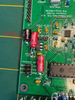
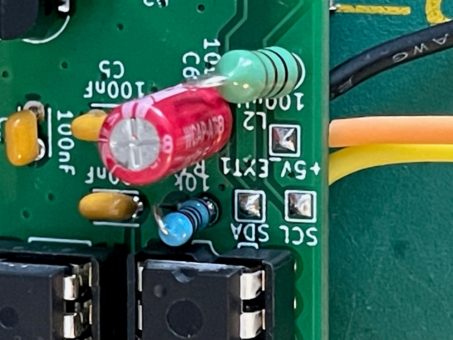
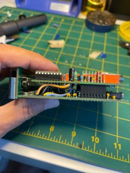
There are 3 electrolytic capacitors that might interfere with quadband pcb when it is stacked on top of main pcb. These caps need to lay flat on their belly to get out of the way. See photo below:
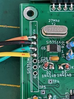
Now we need to connect the +5V, GND, SDA and SCL lines of the QuadBand Pcb to Main PCB:
These photos show 4 electrical connections that needs to be connected with short piece of insulated wires between Main board and QUADBAND pcbs. On QUADBAND you will see 3 pads named as +5V, SDA and SCL. Ground can be any ground point close to these pins. I soldered these connection cables on solder side of QUADBAND pcb to keep the length of wires as short as possible.
These pads will be carried out with 4 short wires to SI5351 module pins as shown in the photos. Try to keep the wires as short as possible. 2” (50 mm) wire length should be good enough for connection length.
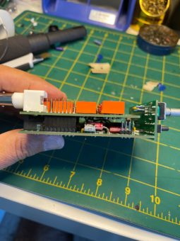
After soldering all 4 connections mate the QUADBAND pcb with main pcb as shown in the photo. Check in between two pcbs for any components that might touch quadband pcb solder side. If that’s the case isolate with an electrical tape or bend the component to get out of the way on main board. Also watch out if ISP pins are close to or shorting QUADBAND pcb solder layer.if that’s the case again isolate with electrical tape.
– Tuck in excess connection cabling between two boards to get them out of the way.
For testing and adjustment of QUADBAND PA+LPF pcb please refer to uSDX TriBand PA+LPF section. It’s not different than original PA adjustment.
FIRMWARE:
For QUADBAND to be active and usable uSDX firmware version V1.02t or newer version should be used. Any other version won’t work with QUADBAND PA+LPF band board as there is no band select provision on older versions suitable for this board.
You can download the latest firmware from this link:
https://github.com/threeme3/QCX-SSB/blob/feature-rx-improved/QCX-SSB.ino
To activate QUADBAND board just uncomment this define: (Uncomment means remove // )
#define LPF_SWITCHING_WB2CBA_USDX_OCTOBAND 1 // Enable 8-band filter bank switching: non-latching relays wired to a MCP23008 GPIO extender on the PC4/PC5 I2C bus; relays are using GND as common (ground), GP0..7 used by the individual latches K1-8 switching respectively LPFs for 80m, 60m, 40m, 30m, 20m, 17m, 15m, 10m
The rest of the defines depends on what configuration your uSDX TriBand rig is build, meaning LCD or OLED, 25 mhz SI5351 Module or SI5351 smd chip with 27mhz crystal.. Those selection of defines should be uncommented to match the uSDX TriBand build configuration and has nothing to do with QUADBAND define. Please refer uSDX TriBand design build article for details.
What are those 3 jumpers at the solder side of the pcb???
JP2, JP3 and JP4 is to connect pin header pins to SDA,SCL and +5V lines of QUADBAND. This is a provision if any fellow ham designs their own uSDX main pcb and decides to use this quadband pcb in their design as their band switching board. These jumpers gives them a clean straight through connection via header pins without messing with cable connection.
These jumpers are not to be used in existing uSDX TriBand design! IF YOU ARE USING ORIGINAL uSDX TriBand main board to use with this QUADBAND pcb then DO NOT SOLDER JP2,JP3 and JP4! It will just short everything if you do so!
So is this thing really working?
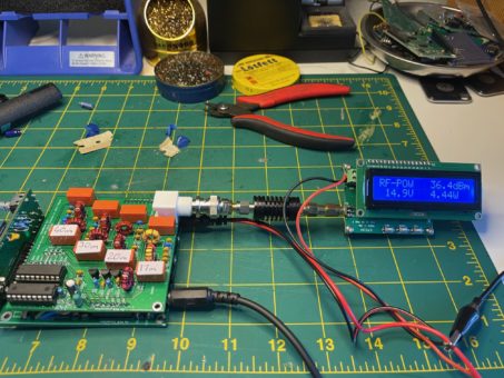
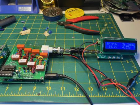
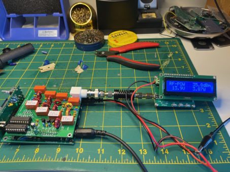
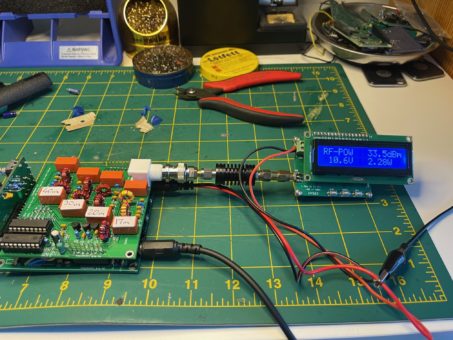
Here are some RF power output measurements:
40m Band:
30m Band:
20m Band:
17m Band:
I hope ham community will find useful this QUADBAND – 4 band auto switch PA+LPF pcb to upgrade their uSDX TriBand. It certainly adds a different perspective and user pleasure to uSDX TriBand. Now PA Mosfets are feeling much safer!
I would like to thank:
– Giudo Ten Dolle, PE1NNZ for his brilliant uSDX firmware.
– Manuel Klaerig, DL2MAN for his Serial Resonance LPF application for uSDX and relay selection scheme inspiration.
– My Friend Ken Delap, KX9U, for his LPF values and endless testing and support.
73,
Barbaros (Barb) Asuroglu, WB2CBA
NY,U.S.A SEPTEMBER 2021
wb2cba@gmail.com

