uSDX Multiband Serial Resonance Low Pass Filter
uSDX V1.02 PCB Goes Efficiently Triband!
I was following with admiration Manuel Klaerig, DL2MAN’s work on designing and testing his efficient serial resonance Band filters for his uSDX sandwich pcb design.
You can follow Manuel’s work and thread here:
I wanted the same efficiency and multiband capability on my V1.02 PCB but I knew that my RF knowledge is no way near Manuel’s when compared so I did the next best thing, I shamelessly copied his work and adapted to my V1.02 PCB! :) Of course with Manuel’s guidance and approval and I thank him for his help and nice gesture.
If you are not familiar with uSDX and V1.02 pcb and the add-ons then here are the links to my articles:
https://antrak.org.tr/blog/projeler/usdx-an-arduino-based-sdr-all-mode-hf-transceiver-pcb-iteration-v1-02/
https://antrak.org.tr/blog/usdx-sdr-ssb-sota-transceiver-battery-pack/
https://antrak.org.tr/blog/projeler/linear-rf-power-amplifier-for-usdx/
You can also check IOgroups forum of uSDX which has tons of useful information:
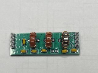
I designed two types of Serial resonance LPF module pcb for uSDX V1.02 PCB. One is called the serial resonance band filter module and is exactly the same format as uSDX Multiband module.
Here it is:
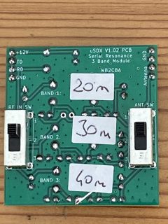
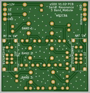
And the other one is called Serial Resonance 3 Band Module” or “The Swiss cheese module” :)
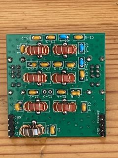
The Serial Resonance Band Filter Module:
The serial resonance band filter module is for building single band modules for each band and swap them for the desired band. The function is same as multiband modules but these are more efficient serial resonance lpf modules. What do we mean by more efficient? It means we get RF power output with less milliamps of current which is great when we are operating on batteries.
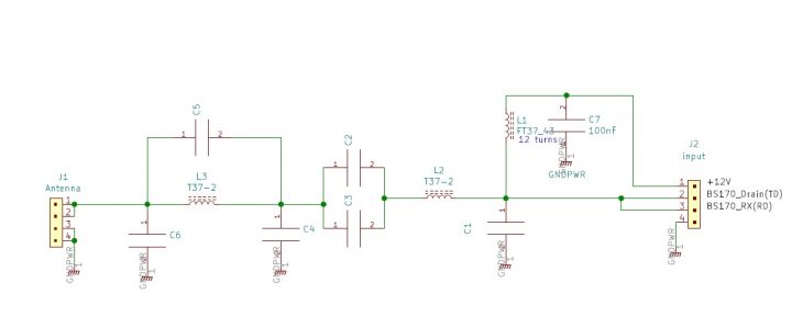
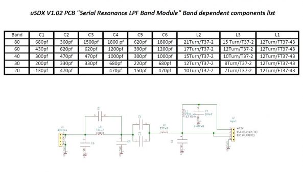
Here Is The Schematic of Serial Resonance Band Module:
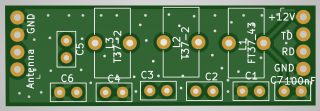
L1 is FT37-43 toroid with 12 turns of AWG 24 or 26 wire. This inductor is not band dependent and can be wound the same way for all bands.
The rest of the toroids and capacitors are band dependent and we will talk about them a bit later…
For band dependent T37-2 toroids I used AWG26 wire.
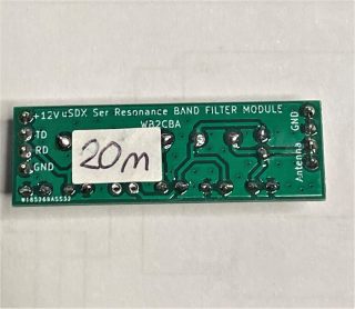
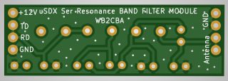
Here are the pcb layouts for Serial Resonance band module:
The Serial Resonance TriBand Filter Module:
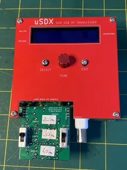
This module is also plug in type like band module but consists of 3 independent serial resonance low pass band filters for three different bands of your choice which can be selected with two 3 position slide switches.
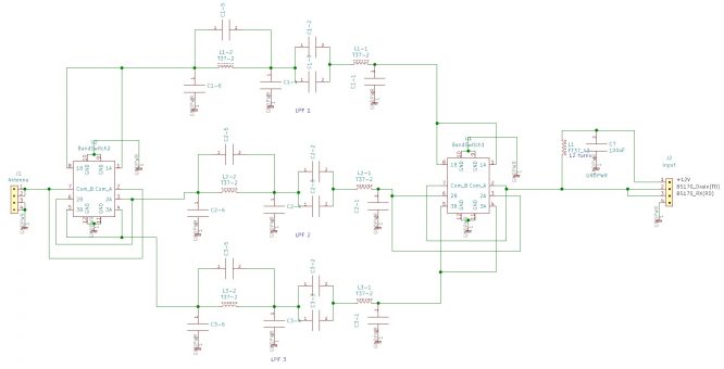
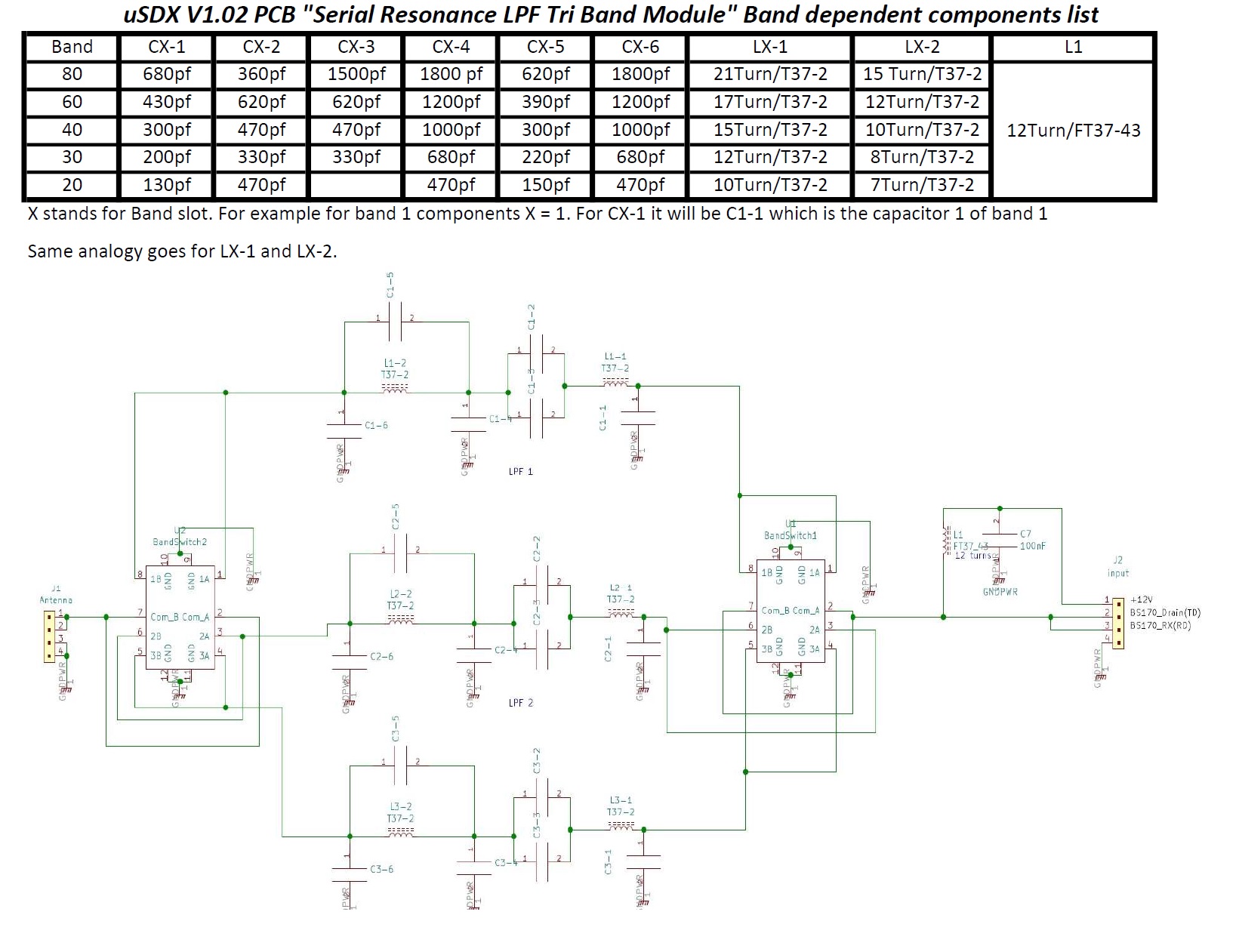
Here is the schematic:
Switch 1 is used to switch PA input between bands and switch 2 is to switch output of the band low pass filter to antenna.
The serial resonance filters are identical in schematic and only the values of components are band dependent and varies for each band.
3 bands can be build mix and match meaning that 3 bands of your choice. Don’t forget which band slot holds which band and choose the right components from below posted table for the right band you decide to build! That’s it!
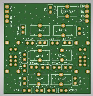
Here are the pcb layouts:
Component side layout
Solder layout
Let’s talk about building these modules:
Building serial resonance band module it is pretty straightforward:
The toroid coil turns for each band and the capacitor values for each band can be selected from the table below in this article. The important thing to be careful when building these modules is 4 pin headers and which side of pcb they are soldered. For that please refer to the photos above.
Serial Resonance TriBand Module build:
Serial Resonance triband Module is build in the same way as single band module times three!
The band dependent capacitor and toroid turn values can be grabbed from the relevant table below.
RF IN switch and ANT switch has 3 positions marked as 1, 2 and 3. These correspond to 3 bands. The bands are marked with Band1, Band2 or Band3 with “:” to label the relevant band.
These band switches are soldered on solder side of the pcb as in the photo.
All the toroids and capacitors for example for band 1 has labels as C1-1 which means that band 1 capacitor 1. So is the toroids for example for band 1: L1-1 meaning L1 of band 1.
For slide switches I used these ones from Digikey:
https://www.digikey.com/en/products/detail/e-switch/EG2301A/301966?s=N4IgTCBcDaIKIHECMBOALGgtAOQCIgF0BfIA
Digikey code: EG1944-ND EG2301A Switch SLIDE DP3T 200MA 30V
This is important:
When switching bands both slide switches should be in the same position meaning that if we want to switch to band 1 then both RF IN switch and ANT switch should be in position 1. If not then you can smoke your BS170 PA mosfets!!!
Also make sure that you are switching to a band which is selected in uSDX screen not to a different band!
PA Bias adjusments:
- Keep menu item 8.2 PA Bias min at 0.
- Connect Antenna output to a rf powermeter.
- Connect uSDX TRX to a DC supply of 12 volts with an amperemeter in series to measure current draw while in TX.
- Now choose CW mode for the band you wish to test and calibrate on.
- Select menu item 8.3 PA Bias max
- Start increasing PA Bias max until you see no increase in RF output power but an increase in milliamp current draw meaning that you are now over driving the PA so lower PA Bias max a notch until to the starting point of your RF output maxes out and milliamp is just starting to increase and your RF output stays constant. Leave it there.
Happy QSO’s with your now efficient uSDX QRP SDR TRX and Thank you again Manuel, DL2MAN for your serial Resonance efficient LPF.
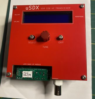
Serial resonance LPF Modules on uSDX V1.02 PCB when plugged in:
uSDX Serial Resonance band module files
Barbaros Asuroglu aka Barb WB2CBA
NY 10/21/2020
wb2cba@gmail.com

