uSDX SDR SSB SOTA TRANSCEIVER BATTERY PACK
Preparation
In my last article I tried to put together my experience of building uSDX SDR SSB Transceiver that is based on Arduino. You can read that article in this link:
In this second part we will build a rechargeable battery pack for uSDX SDR SSB Transceiver so that we can take with us in our backpack and enjoy hours of SOTA (Summit On the Air) QSO experience.
When I first started my quest for a small and light SOTA backpack transceiver I never imagined I will end up with such a fun and efficient portable SSB gear. It is absolutely a joy to work digital modes with Guido, PE1NNZ’s brilliant SDR SSB project.
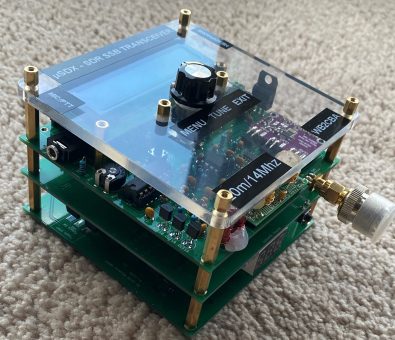
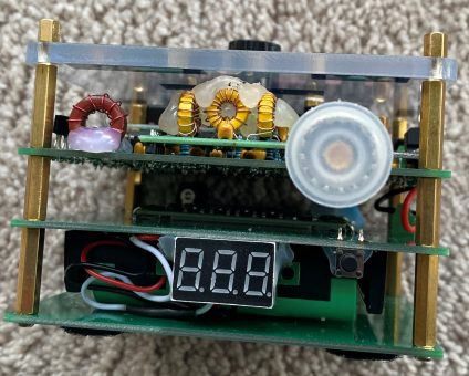
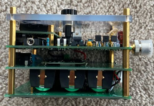
After testing and using uSDX for sometime I started to think about a dedicated battery pack that can be bolted underneath the uSDX V1.01 pcb. Using RC aircraft lipo batteries wasn’t the most ideal solution. Ofcourse casing would be a problem. Then I glanced at my NanoVna vector analyzer and voila! Who cares about a case! I can stack pcbs on top of eachother with metal spacers and a lexan face plate on top and a spare pcb as bottom plate then we are done. Ugly but efficient!
This is the end product uSDX SDR SSB SOTA rig with battery pack in the middle.
uSDX Battery Pack Details:
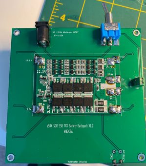
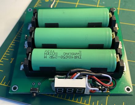
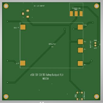
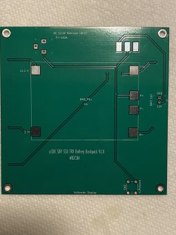
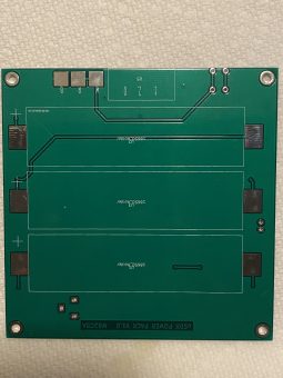
This is how the battery pack pcb looks like. The size of the pcb is same as the size of uSDX V1.01 pcb with same mounting holes. This is on purpose to bolt it under the uSDX SSB PCB with mounting spacers.
It consists of:
– A BMS(Battery Management System) module
– 3 x SAMSUNG 3.7V / 2500 mA 18650 li-ion type batteries.
– A barrel jack for charging and powering uSDX SSB with external power source
– 3 x SMD Type 18650 battery holders
– A SPST toggle switch for powering the uSDX SSB Transceiver.
– A voltmeter to monitor battery voltage.
A tactile switch to activate voltmeter when needed.
Here is the schematic of Battery pack:
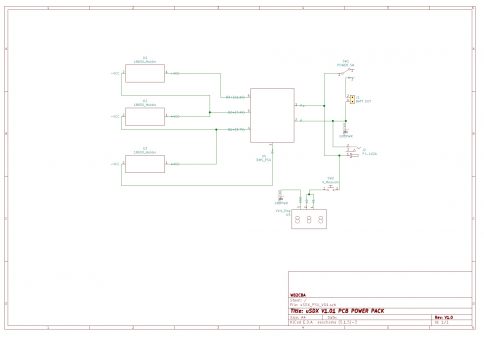
uSDX V1.01 Battery Pack Schematic
When I first decided to design this battery pack I realized that I needed a li-ion charge module and an under voltage monitor not the discharge batteries beyond damage point which altogether consists a simple Battery Management System or BMS in short. Every li-ion battery powered gadget we own has some degree of BMS built in.
The most crucial part was the BMS unit and I started my search on web to find a BMS module. To my surprise I found many of them and they were dirt cheap in the order of couple of dollars up to 10 dollars US!
Here is an example of one:
https://www.amazon.com/Polymer-Lithium-Battery-Protection-Charging/dp/B07GWQ2LX8
This is similar to the one I used.
These BMS modules were designed to be strapped on 18650 batteries which means they all come with the same size and form pretty much. Dimensions are 56 mm x 45 mm x 1.2 mm in metric sizes.
These BMS modules are almost in every Chinese electronics warehouse site. They are very cleverly designed. These can balance charge the batteries which is a desired method of charging as battery characteristics might differ slightly between each battery. Also they monitor over discharge, and under voltage protecting the battery.Short circuit protection comes with the package.
After deciding to use one of these modules the rest was pretty simple. Get the module and parts needed, put together a perfboard to test all works fine then design a pcb to hold all in place!That is exactly what I did
I used 3 x 18650 type Li-ion battery in series which means when fully charged they deliver 12.6 volts output voltage with 2500 mA current which is more than enough to operate uSDX which draws 500 mA on TX. The battery capacity is theoretically enough for 5 hours continuous TX which realistically will never happen. A full day SOTA qso will be possible with this Battery pack.
BMS module cuts off power around 2.3 Volts per battery which is 8.6 Volts.
Building uSDX V1.01 SSB bolt on battery pack:
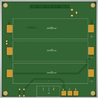
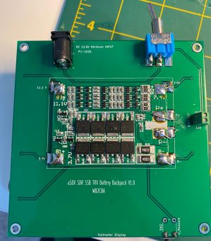
These are top and bottom view of uSDX Battery pack PCB.
Ordering the pcb:
Gerber Files are in uSDX_PSU_V01_GERBER_FILES_06_30_2020
You can use this file to order pcb of uSDX battery pack from any pcb manufacturer. I use www.pcbway.com in China. They have reasonably cheap prices and fast return time if you choose DHL or FEDEX for delivery. 10 pcb costs 5 US Dollars + shipment.
For ordering you choose default values. Just enter pcb size as 98mm x 98 mm and choose how many pcbs you need. Then you add your selection to cart and upload gerber file to them which is this zip file. You don’t need to extract zip file just upload as it is.
They will review your gerber for suitability for manufacturing and send you an email notifying you that your pcb is approved for manufacturing and waiting for your payment. You can pay with paypal.
Components and where to buy them:
– BMS Module:
This is the main part of the battery pack as we discussed above.
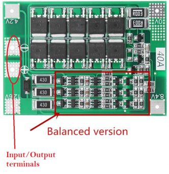
Use one similar to this photo.
Important points when selecting your BMS Module:
– It should be for 3S which means for 3 x 18650 batteries
– It should have balanced charging circuit area populated as in the photo.
– Must have a single input/output terminal as shown in the photo above
– Dimensions of the module should be 56mm X 45 mm X 1.2 mm
I used this BMS Module from Amazon.com:
You can use any similar BMS module from Amazon, Ebay or Aliexpress.com.
Here are some links to similar BMS Modules:
– 18650 Battery Holders:
18650 li-ion battery holders are sized for 18650 batteries and they should be the smd type with smd tabs at each end of the holder.
I used these ones from Amazon:
You need three of them for battery pack
18650 type Li-ion Batteries:
Any 18650 Li-ion battery can work. There are ridiculous claimed ones can be found in the market such as 3.7V/10000 mA! I generally stay away from them. It is always a good idea to stick with known brands like Panasonic, Samsung etc. I used Samsung in mine. Here is the link where I purchased them:
Voltmeter Display:
The voltmeter is a cheap simple 0 to 30 volts LED 7 segment voltmeter module which allows to monitor battery voltage when needed.
I bought mine from amazon:
Here are some links for similar voltmeter display from Ebay etc:
Sparkfun, and Adafruit also sell these voltmeters.
– 5.5 mm x 2.1 mm Barrel Connector for Power supply:
I used pcb type through hole 5.5 mm x 2.1 mm Barrel male connector from CUI, PJ-102A on my pcb.
Here is the link from Digikey:
This is not critical. Any pcb type male barrel connector should fit.
SPST Toggle switch for Powering on/off uSDX SSB pcb:
I used these from amazon:
This can be a SPDT Toggle switch also. This is not critical. Any toggle switch can be used.
– 6 mm Tactile Push Button Switch:
This is an ordinary tactile switch. This is used to power voltmeter when needed. This way voltmeter won’t be a burden on the battery when idle.
Here is a link from Digikey as an example:
Let’s build it!:
Here are some tips building uSDX Battery Pack.
– Start with the BMS Module. Use double sided tape to fix the BMS Module in it’s place carefully orienting the output terminals by matching the terminals on the pcb.
As you can see BMS is aligned with the white BMS module border line and all terminals are soldered with short wires to each of the pads aligned on the pcb. Keep the wires as short as possible.
– Now turn the PCB upside down and solder three 18650 SMT battery Holders in place.
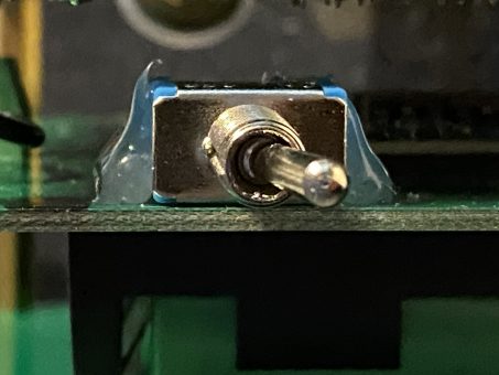
– Time to solder SPST(or SPDT) Toggle switch in place.
Solder straight to the pcb as shown on the photos above.
– Now Solder Barrel Connector as shown in the photos above.
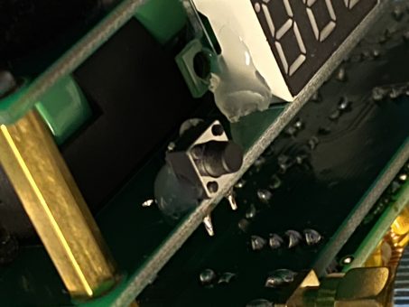
– Bent wo pins of Tactile switch 90 degrees and solder to the pcb holes close to the outer edge of the pcb as shown in the photo.
– Solder Voltmeter Display as shown in the photo. R and W are 12V and B is Ground. The ones I used had White and Red for 12V connection and Black wire for Ground connection where these R,W and B are coming into play. If yours have only Red and Black wires then use R pad for Red wire and B pad for Black wire.
Now you will notice that somethings are not right! The toggle switch and tactile pushbutton is not tightly secured and there is no attachment for voltmeter. Now the hot glue gun comes to play to save us. You can fix the Voltmeter to the pcb with a bit of hot glue or super glue depending on your choice. Also a bit of hot glue to secure the Toggle switch and tactile switch in place.
Here in these photos you can see hot glue gun job! It is not the best in terms of aesthetics but works.
Operating and Testing the Battery Pack:
When fully charged Battery pack voltage is 12.6 volts. Which is 4.2 Volts per cell. To charge the batteries a voltage of minimum 12.6 volts is needed. I generally use my variable power supply at 13.0 Volts. It can be pushed up to 13.8 volts but then the BMS mosfets are heating up as the charge current rises up as high as 4.5 amps. A heatsink is a must for the BMS mosfets under 13.8 volts. Do not push beyond 14.0 volts as it heats up BMS mosfets and they can be a victim of nasty smoke disaster! :)
At 13.0 volts charge current is 2 amps if the batteries are low in charge. As the battery voltage rises by charge the charging current decreases proportionally. Around 13 volt charge voltage keeps the heat on mosfets at reasonable levels without a heatsink.
For a simulated usage test I connected a DPDT relay to an Arduino with two resistors to simulate TX and RX current consumption of uSDX SSB TRX operation under battery pack. Then I programmed the Arduino to simulate a full continuous FT8 operation scenario such as continuous 15 seconds TX and 15 seconds RX which is %50 duty cycle. On RX uSDX SSB TRX draws approximately 60 miliamps and on TX 500 miliamps max. Beginning of the test I had fully charged batteries at 12.6 Volts. After 5 hours of this test scheme I ended up with 10.0 volts in battery pack which I think is not bad at all.
We will hardly use this RX/TX scheme in real life. There will be more pause between transmissions. So my conclusion was the battery pack can operate one day of SOTA QSO session without any problem.
So here it is, I achieved my dream of a highly portable and light battery powered SOTA backpack QRP SSB transceiver with this great uSDX project. I would like to thank again to Guido, PE1NNZ for his great design and firmware skills. Also all of my fellow hams on uSDX IOGROUPS forum for their support, great knowledge and friendship. Thank you.
Barb, WB2CBA
July 2020, NY
wb2cba @ gmail.com
uSDX_PSU_V01_GERBER_FILES_06_30_2020
uSDX V1.01 Battery Pack Schematic
– This pcb design can not be used commercially without the consent of Barbaros Asuroglu WB2CBA.

