ATUPWR – ATU + Power Bank Combo for Field Portable Operations
ATUPWR is a Power bank and Automatic Antenna tuner combo for QRP Portable operations.
I always operate portable as I don’t have an antenna in my apartment building as it is banned. In my go bag I carry 3 things apart from antenna. My TRX, ATU and Battery pack.
For some time I was pondering of combining ATU and battery pack into one unit to carry a compact 2 in 1 unit.
I came up with this solution which is basically a miniaturized version of ATU 100 adapted to work in QRP limits and 3 cell 18650 battery block with BMS.
All build details, Gerber files, Fabrication files, Firmwares and schematics for AtuPwr is in this link:
https://github.com/WB2CBA/ATUPWR—Portable-Automatic-Antenna-Tuner-for-HF-bands-With-Battery-Bank
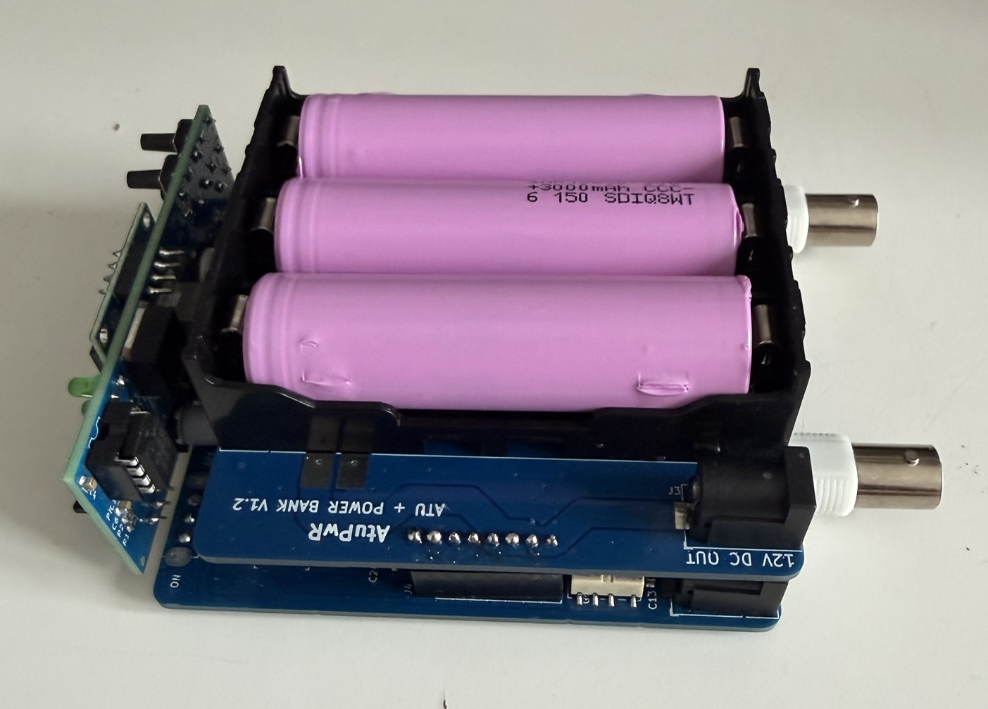
ATUPWR unit consists of 3 pcb boards,
- Powerbank PCB,
- Automatic Antenna Tuner PCB,
- Control Interface and Display PCB,
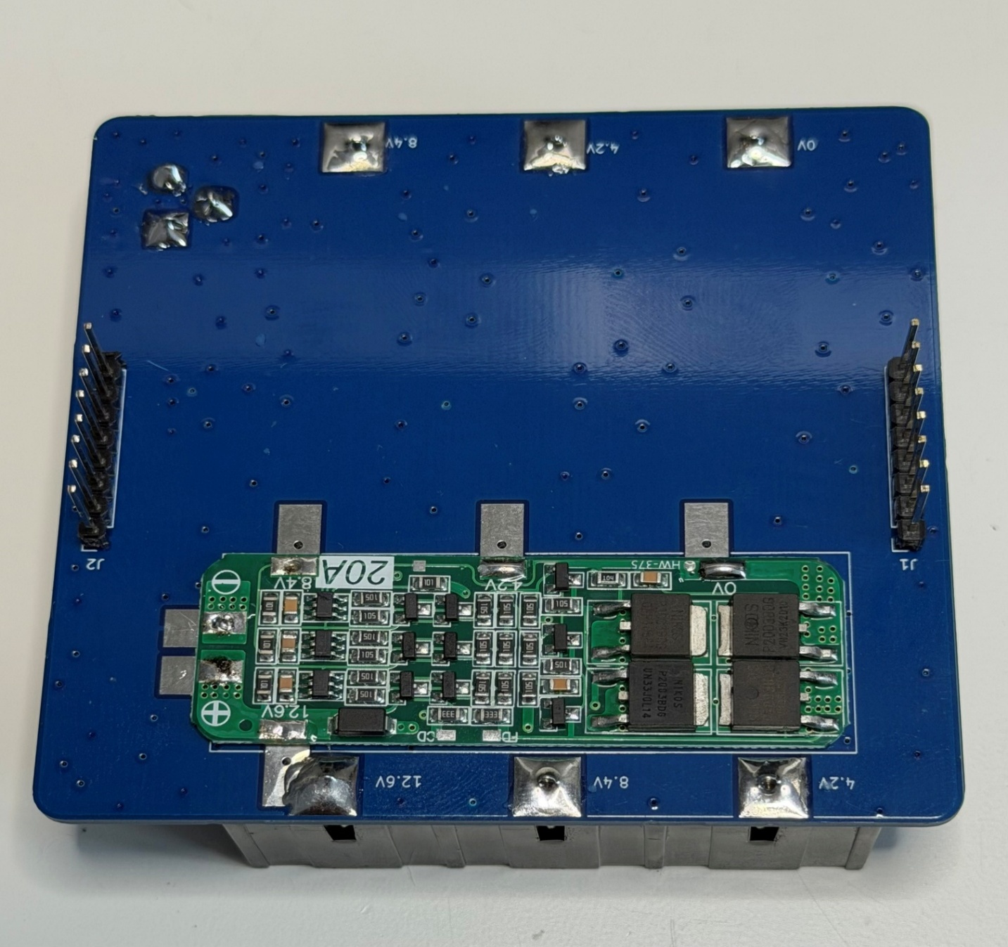
POWER BANK PCB:
Power bank max output voltage is 12.6V fully charged. Power bank utilizes 3 x 18650 Li-ion batteries and a 3S 20A BMS (Battery Management System) module. This module can monitor battery Overvoltage/Undervoltage, also charging balancing.
Here is Power bank board layout:
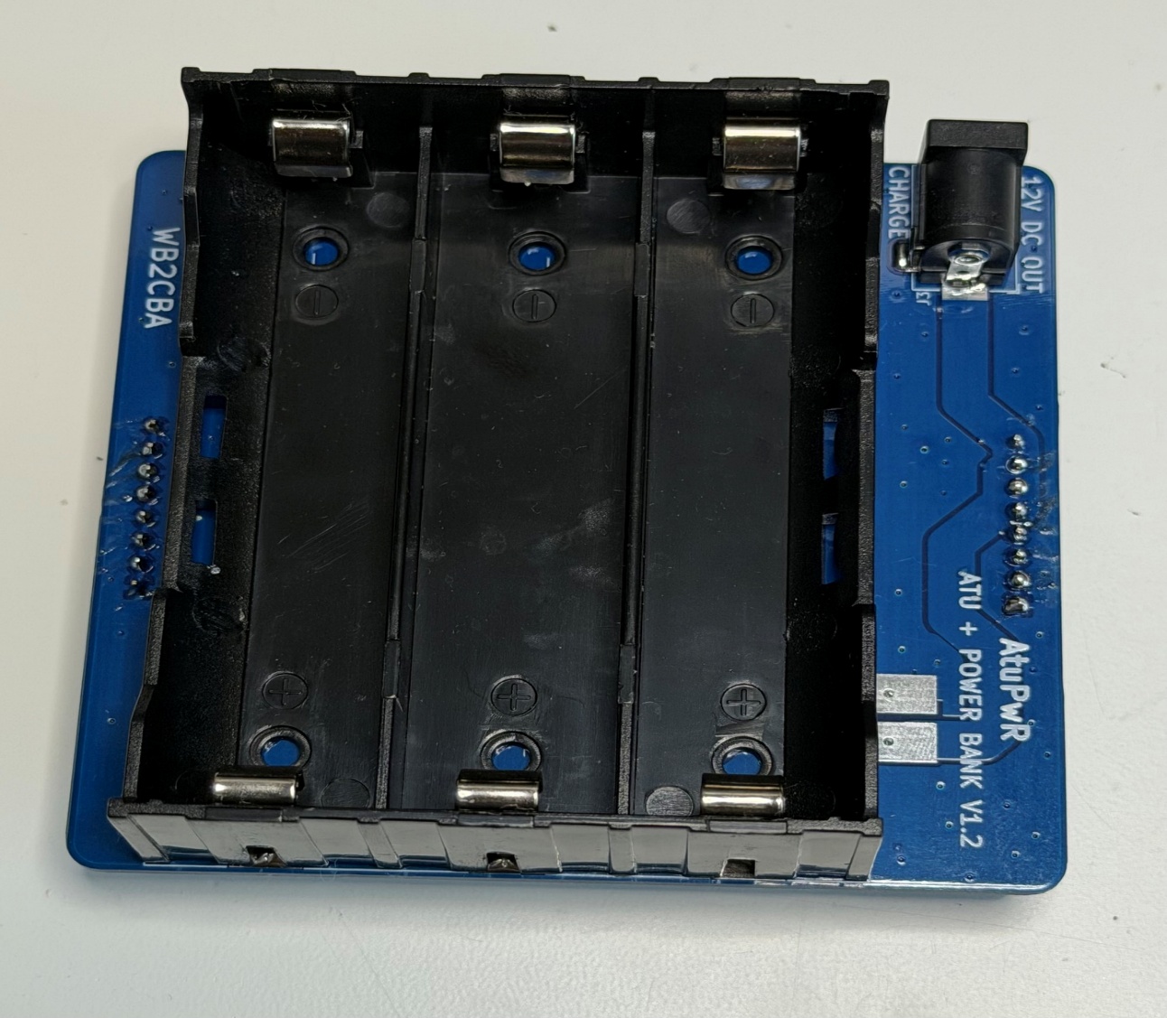
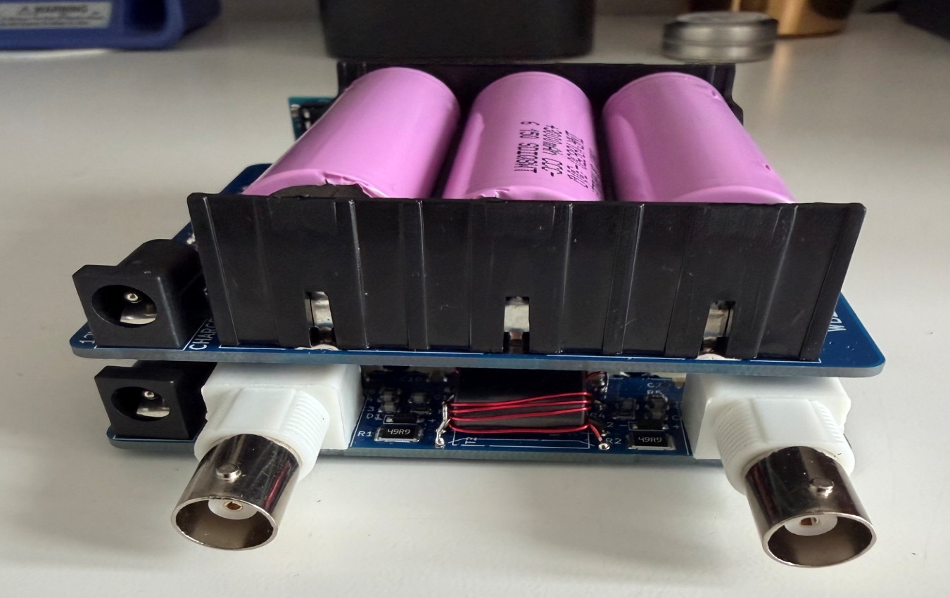
Power Bank PCB has a 5.5×2.1 DC Barrel Plug female adapter. This plug can be utilized to power
any 12V QRP transceiver. 18650 batteries has 2500 mA nominal capacity which can give couple of hours of operating time with most QRP rigs. Also this Barrel connector plug can be used for charging using a 12.6 Charging adapter.
This wall charging adapter in the link is used for charging which puts out constant current 12.6V: https://a.co/d/0at9GylA .
These chargers are common and cheap so no charger facilitated in the PwrAtu design to keep simple and light.
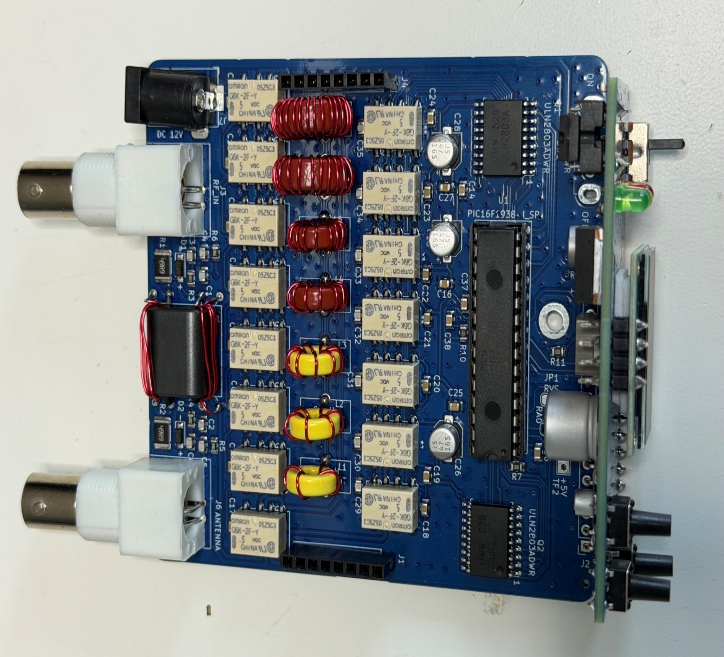
Automatic Antenna Tuner PCB:
Automatic Antenna Tuner PCB is N7DDC David Finitsky’s ATU 100 7×7 Automatic Antenna Tuner adapted and modified to work as a 20W max QRP ATU. Operation of ATU is identical to ATU 100.
For more details on ATU100 and its operation please refer to this link:https://github.com/Dfinitski/N7DDC-ATU-100-mini-and-extended-boards
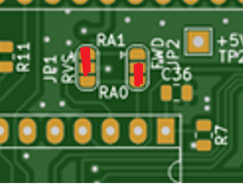
ATU BOARD JUMPER SETTINGS:
Solder red marked pads
ATU BN43-202 Binocular Coil:
(Note that BN43-1502 used in examples below though same applies to BN43-202 binocular)All Toroid and Binocular coil can be wound using AWG28/0.35mm magnet wire.
Winding and installing the binocular toroid: To wind the BN43-202 inductor core start at one side of the core and feed the enamel copper wire 5 times through the hole. Every time the enamel copper wire goes through the hole counts as one turn.
After completing 5 turns in the first hole now start from the second hole on the opposite side of binocular core at the second hole. When winding the toroid, try and keep the wire as close as practical to the toroid. When you finish it should look like the example in the photo below:
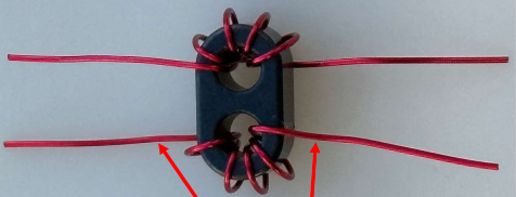
NOTE: the entry and exit points of the wires (below and above) on each side of the binocular toroid.
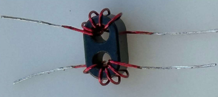
Wind your binocular toroid in the same manner. Ensure that the windings do not overlap and are evenly spaced.
Remove the enamel coating from the wires by either sanding or scraping with a sharp modeling knife and tin the wires with solder as shown below:
Next cut two 1.5” (~35mm) insulated electrical wire. These two wires will be fed through the holes of binocular core (white wires in the photo), and soldered to the PCB as shown in the photographs below:
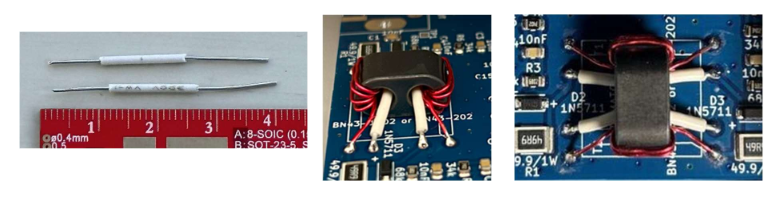
Adjust the length of these insulated through wires as needed before soldering – take your time to ensure a neat and uniform installation.
Winding ATU Toroid:
For ATU Toroid AWG28/0.35mm Magnet wire can be used.
There are altogether 7 toroid to wind.
These are:
- 3 x T37-6 type
- 2 x T37-2 Type
- 2 x T50-2 type
Winding Turns for these Toroid are listed below:
L1 – T37-6 – 4 Turns
L2 – T37-6 – 6 Turns
L3 – T37-6 – 9 Turns
L4 – T37-2 – 11 Turns
L5 – T37-2 – 16 Turns
L6 – T50-2 – 21 Turns
L7 – T50-2 – 30 Turns
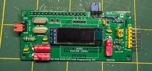
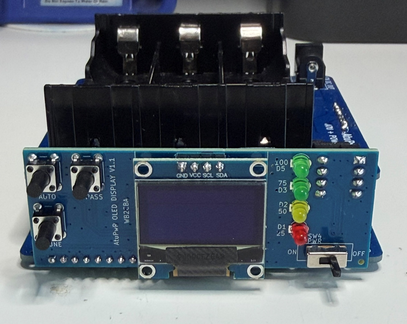
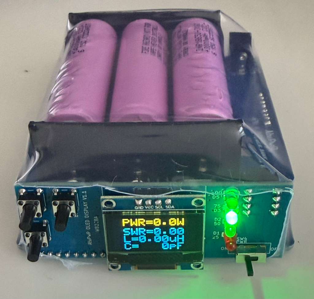
Interface and Display PCB:
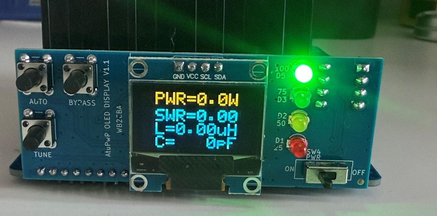
Interface and display pcb have couple of functions. It has control switches to control ATU functions, has also an 0.92” OLED Display for displaying TX power, antenna power, SWR and Power/SWR efficiency. Also displays L and C values of tune. Interface and display pcb have also a four LED battery level indicator. Battery levels are indicated as 100% with a green LED, 75% with a green LED, 50% with a yellow LED and 25% with a red LED. When battery discharge is below 25% red LED flashes warning that a battery charge is imminent.
There is also a slide switch which turn on and off ATU+ interface display board. Power bank is always on and does not consume any battery if not used.
- ATU main board and interface display board has two PIC micro controllers.
- ATU utilizes a PIC16F1938 micro controller and Battery Level display utilizes a PIC12F675 micro controller.
These microcontrollers can be programmed using PICKIT3, PICKIT4 or PICKIT5 microchip programming adapters using posted .hex files in this GitHub files section. These programmers are common in online shopping sites like amazon.com
Here is a link for PICKIT3: https://a.co/d/0hhkPumv
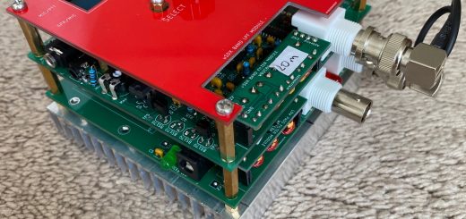
Here are some photos that will help for your build:
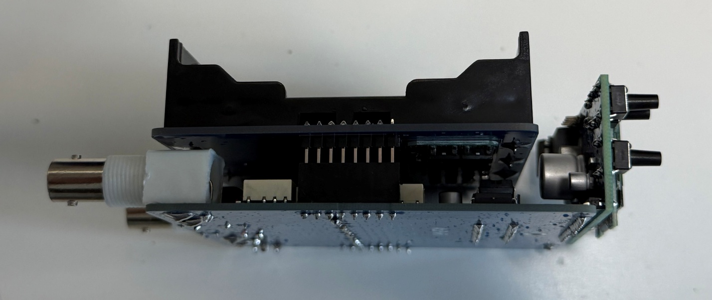
Sideview of stacked boards.
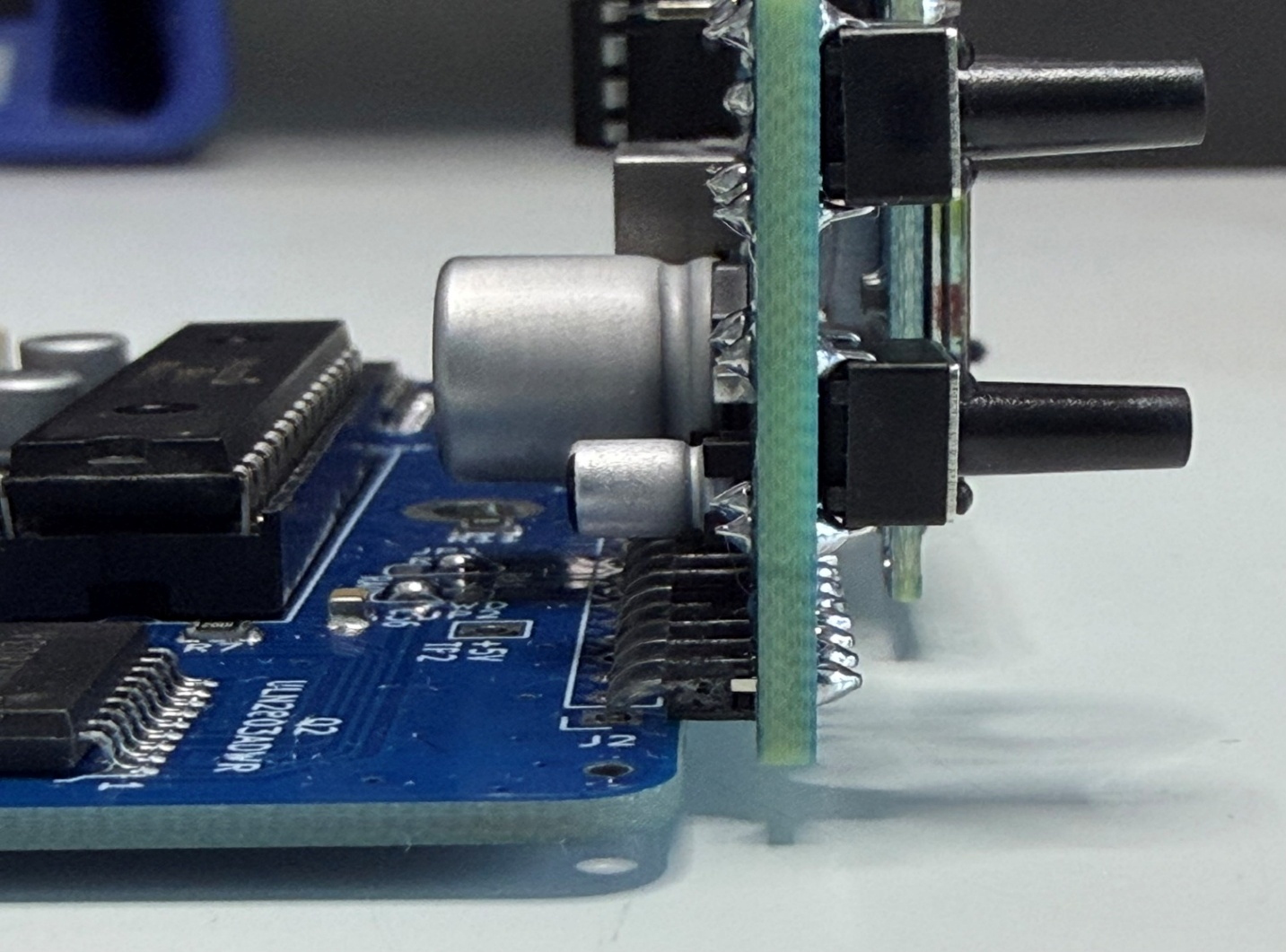
90-degree 2.54 pitch male header is used to connect display interface to ATU as shown.
For SMD part soldering I designed boards to be manufactured by JLCPCB of China. This makes
life easy as these boards arrive pre-soldered of all smd parts.
Here is the link for JLCPCB: www.jlcpcb.com
Through Hole Part BOM List:
- 1 x OLED Display: https://a.co/d/0e0w84aL
- 2 x BNC PCB Type connector: https://a.co/d/00Qw3aV2
- 1 x BMS Module: https://a.co/d/09KkfIuF
- 1 x 3-18650 Battery Holder: https://a.co/d/0ct3JXyp
- 2 x Green 3mm LED
- 1 x Yellow 3mm LED
- 1 x Red 3mm LED
- 3 x T37-6 Toroid, 2 x T37-2 Toroid, 2 x T50-2 toroid, 1 x BN43-202 binocular core :
- 1 x 28 pin skinny DIP IC socket: https://a.co/d/0bKs36lj
- 1 x 8 pin DIP IC socket: https://a.co/d/08990Qoa
- PIC16F1938 Microcontroller :
- PIC12F675 Microcontroller:
https://www.digikey.com/en/products/detail/microchip-technology/PIC12F675-I-P/459171
- 17 mm male 2.54 mm pitch pin header : https://a.co/d/0cHgaR7P
This pin header is used on battery board for stacking ATU board to Power bank board.
- 2.54 mm pitch female header: https://a.co/d/06al5QaQ
This female header is used on ATU board for stacking ATU board to Power bank Board.
- 3 x 6mm x 6mm x 12mm Tactile switch : https://a.co/d/00haVKzx
- Slide Switch: https://a.co/d/0hbDwx5R
- DC Barrel Connector PCB type : https://a.co/d/0g5969O2
- 90-degree 2.54 mm pitch male header: https://a.co/d/0j8ei4eA
I didn’t design a case for AtuPwr. Instead, I opted to use Clear Battery Heat shrink wrap to wrap all around electronics and batteries to prevent any short circuits. A 3D case might be a more elegant solution.
AtuPwr solved the problem of carrying multiple units to operate in my backpack which is a breeze to carry.
Barb WB2CBA
06/2026, NJ