uSDX V1.01 and V1.02 PCBs – Adding OLED Display, CAT and USB Programming Capability
uSDX V1.01 and V1.02 PCBs – Adding OLED Display, CAT and USB Programming Capability
When I designed V1.01 and V1.02 Pcbs I never thought of a fast programming option and didn’t even include an ISP connector! Shame on me!
These pcb designs are almost a year old now and I could never anticipate Guido will release so many versions of improved firmware over the coming months back then.
Now it is really pain in the back to pry out the Atmega328p and swap into Arduino and then pry back from Arduino to V1.01 or V1.02 pcbs! And knowing that so many hams adopted these designs and going through all these hassels made me feel guilty to solve this problem once and for all! And here we go!
After some head scratching I came up with this idea and implementation!
So first of all the main aim was to ease the programming struggle. To do that I needed free Serial UART pins which were connected to the LCD display. So I had to get rid of the LCD display and this gave a nice area to device a replacement PCB to hold all the necessary bells and whistles!
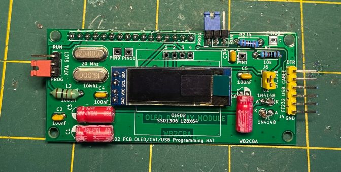
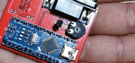
This is the end product of head scratching, OLED/CAT/USB Programming HAT.
I got rid of the LCD display and now we have the option of choosing between two OLED display sizes, 128×32 narrow OLED or 128×64 bigger format square OLED.
Also pcb has two configurable jumpers to choose between normal operation which I called RUN and USB serial cable assisted programming which I designated as PROG. So no more prying out Atmega328p for programming
As this option has usb connectivity in full force why not include all the assistance for CAT(Computer Aided Transceiver) meaning DTR connection so that internal VOX can be eliminated. Now WSJT/X or similar digital mode software can TX with CAT.
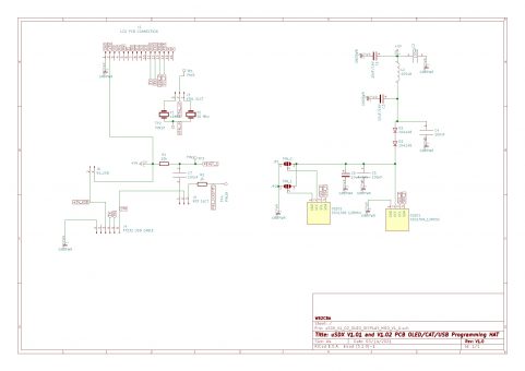
Here is the schematic of the uSDX V1.01 and V1.02 OLED/CAT/USB Programming HAT:
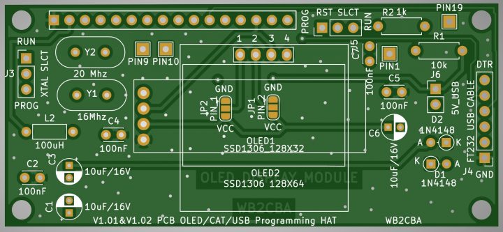
And pcb layout:
Building this modification pcb is pretty straightforward. I will go through step by step.
1- Building the pcb:
The most important thing is to solder the components as flat as possible. This way we can still use the face plate to cover the top of trx.
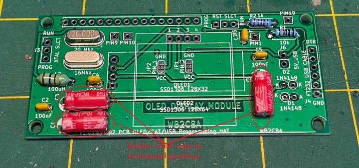
Most of the components are laid out in horizontal fashion. The only exception is 3 x 10uF electrolytic capacitors. These should be soldered flat on their belly so that they don’t stick out and interfere with the top cover.
For OLED I chose to use 128×32 OLED as this is supported very well in Guido’s firmware. The fonts are more condensed. Only disadvantage is fonts are tit bit small.
128×64 OLED:
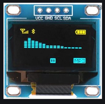
128×64 OLED is bigger in font size. These OLED come in two different pin layout. Some of them are configured as VCC, GND, SCL, SDA:
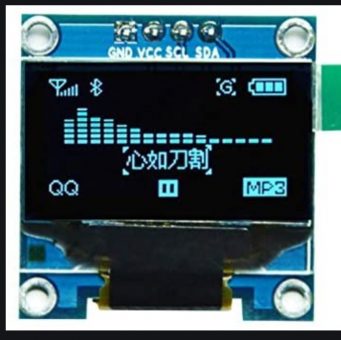
The other layout type is GND, VCC, SCL, SDA:
Both types can be used with this pcb design.
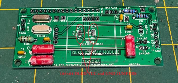
There are two jumpers to configure to suit the type selected.
For example if we select the OLED type with VCC,GND,SCL,SDA pin layout then JP2 which corresponds to pin 1 of OLED display needs to be configured as VCC meaning that we need to solder middle pad of JP2 to VCC pad with a solder blob. Now PIN 2 jumper has to be configured as GND which means JP1 middle pad needs to be soldered to GND side with a solder blob. Then we are done. Now we can solder the OLED in place.
Same jumper analogy goes to the other type of OLED with GND,VCC,SCL,SDA pin layout. Corresponding jumpers JP1 and JP2 needs to be configured to match this type of OLED’s pins.
Do not solder OLED 128×64 in place without first soldering these jumpers with the right configuration! Otherwise you can’t reach to these without removing OLED!
For 128×32 OLED type there is no layout issue. You can solder straight in.
It is a good practice to isolate OLED displays from pcb for any possible shorts. For this I am using 3M double sided tape:
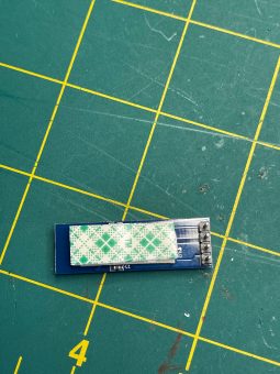
This also raises OLED display to level.
20 Mhz Crystal can be de-soldered from the Pcb of V1.01 or V1.02 radio and used in this pcb as we don’t need it on the radio anyway.
After soldering every component the finished pcb should like this:
2- Now it is time to mate OLED/CAT/PROG PCB with V1.01 or V1.02 PCB:
This procedure is identical for both types of PCBS, V1.01 or V1.02.
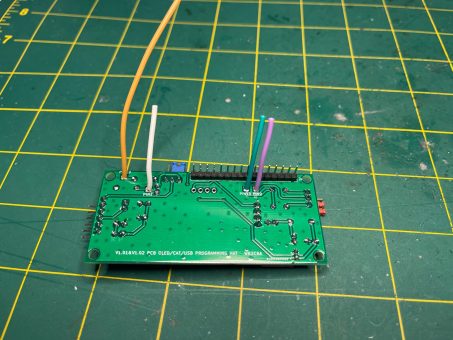
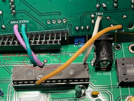
As in the photo 3 relatively short cables and 1 longer one approximately double the size of short cables is needed. Short ones are soldered to PIN1,PIN9 and PIN10 pads on the pcb. Longer one is soldered to PIN 19 pad.
Those 4 cables has to be soldered to pins of Atmega as in the photo above. Pin 1 pad cable goes to pin 1 of atmega328, pins 9 and 10 pad cables goes to pins 9 and 10 of atmega328 and pin 19 pad goes to pin 19.
Now gently push the pcb to LCD display socket and holding spacers. We are done!
Soldering on directly to Atmega328p pins is cruel and crude I know, this is the only way to keep wiring as short as possible. The beauty is we won’t pry it off from it’s socket anyway from now on! :)
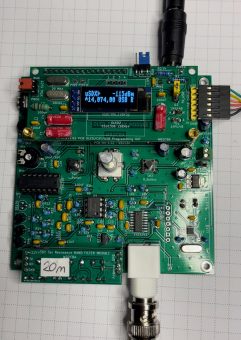
Finished and installed rig should look like this:
3- Using the OLED/CAT/USB Programming Hat:
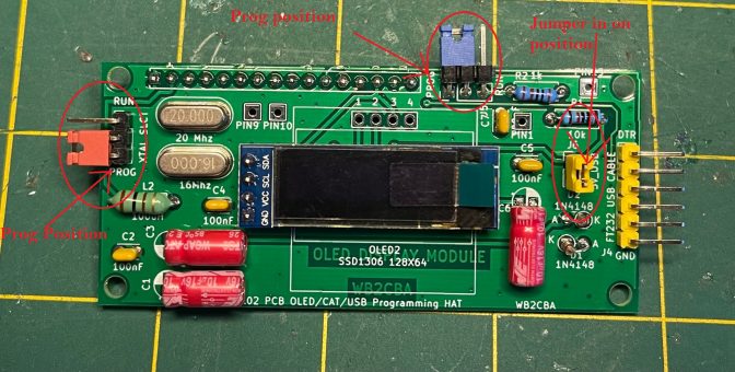
Using this modification is pretty simple. We have 3 jumpers, these are XTAL_SLCT, RST_SLCT and USB_5V
For programming we will set these jumpers as in the photo below:
Now we will plug in USB to Serial cable. For this cable I used this from amazon:
https://www.amazon.com/Sparkfun-Electronics-4446819-FTDI-Cable/dp/B00DJBNDHE
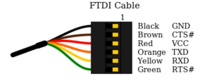
Any of those serial cables will do the job if only these two conditions satisfied:
1- 5V TTL serial logic output
2- FTDI cable pin configuration as below.
We don’t need to power the Transceiver with 12V supply as it’s logic and processor will be powered by USB. This also protects us from accidental TX while programming as there is no 12V connection.
In Arduino IDE we can choose Arduino Uno board and this will do just fine.
Now before we program the V1.01 or V1.02 we need to choose certain #define’s from uSDX firmware to configure the firmware to work with this OLED pcb hat.
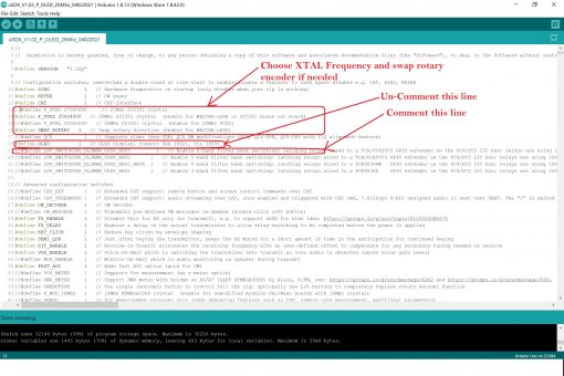
This is the screen shot of Arduino IDE with the latest uSDX firmware version, P.
First thing we should do is to choose our SI5351 working crystal frequency. If we build V1.02 for 27 mhz xtal then the default define of 27 mhz is already uncommented.WE don’t need to do anything for this define line.
By the way to comment means to put two forward slashes like this // and to uncomment means removing two forward slashes in front of the define’s.
If the uSDX is V1.01 or V1.02 is built with a SI5351 Module then we need comment 27 mhz define with two // and un-comment 2500400 mhz define to slect 25 mhz crystal by removing //.
The second thing is to enable OLED display which means we have to uncomment #define OLED 1.
Also uncomment #define SWAP_ROTARY 1 if your rotary encoder works in reverse. This is optional if needed basis.
Now after this we can compile! Oops error! Program can not fit in memory! To go around this issue I commented as in the photo //#define LPF_SWITCHING_DL2MAN_USDX_REV3. No offense Manuel, now it works! :)
Now after all these comment/uncomment business we are ready to compile and program the atmega328p with this pcb hack!
Now after programming/uploading OLED display has to come to life! If that’s the case then programming was successful. Plug out USB FTDI cable and configure jumpers as in the photo below:
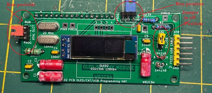
I call this configuration as RUN configuration meaning that V1.01 or V1.02 radio can be used as it is intended to be used, for QSO’s.
4 – CAT:
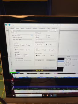
For using CAT first we have to plug in USB to Serial cable. After this for example for WSJT/X software for digital modes needs to be configured as in the screenshot below:
uSDX emulates KENWOOD TS-480 for CAT meaning the digi mode software will think that it is controlling a Kenwood TS-480! They wish! But it works pretty good.
Now V1.01 or V1.02 with OLED display pcb can be controlled to TX with CAT. WSJT/X will automatically go to TX when needed without using the internal VOX of uSDX. Also technically all uSDX CAT functions are active though no frequency to change, no band to select! :)
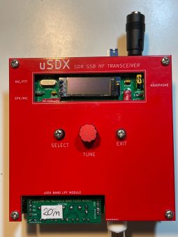
This is SDX V1.02 PCB with OLED Display/CAT/USB pcb installed and with faceplate:
It deserves a new face plate to reborn from it’s ashes! I will design a new face plate as soon as I find some time in my hand from work! Any 3D case design to suit this new form is welcome to be added here! :)
I hope this new pcb hack will bring some fresh and easy programming and usage to V1.01 and V1.02 pcb’s out there.
As always I am adding a zip file at the end of this article with all the necessary files, gerber files and version P firmware configured and ready for this OLED pcb in 25 mhz and 27 mhz options.
uSDX V1.01 and V1.02 PCB OLED_CAT_USB PROGRAMMING HAT FILES
Barbaros Asuroglu aka Barb, WB2CBA,
NY, 04/02/2021
wb2cba@gmail.com

