Linear RF Power Amplifier For uSDX
uSDX on Steroids!
uSDX 10 Watts Linear RF Power Amplifier
After designing and using uSDX V1.02 pcb I was quite happy with the qso results and got positive feedback from the Ham radio community which is great! Meaning that third time is a charm and I didn’t mess up with the pcb design. Pcb 1.00 and 1.01 had their own hiccups.
Here is the link of uSDX PCB V1.02 build details:
So after uSDX V1.02 PCB was designed, built and done there wasn’t much to improve other than enjoy hiking and sota. I did exactly that and it is a great little rig to carry around in backpack.
Then we started to tinker with Ken Delap, KX9U what else can we add to this jewel of Guido, PE1NNZ which is called uSDX!
A linear power amplifier would be a great addition to boost power of uSDX from 3 to 4 watts may be to 10 watts??? Especially for digital modes couple of more watts means a lot. I started to Google for a PA that can be used both on CW and SSB.
When considering VHF and UHF power amps life is relatively easy as there are a lot of hybrid amplifier modules which can be incorporated with fairly less headache. But on HF, search didn’t come up with a suitable PA module to use.
So the pcb had to be designed ground up with discrete components. My first attempt was with Norcal miniboots power amp by Wayne McFee NB6M which is a proven design used with many hams in their diy radios.
Here is the link for Norcal miniboots:
http://www.norcalqrp.org/nb6mminiboots.htm
The only problem was miniboots is for CW, no biasing.
So I found this article about biasing miniboots for SSB.
https://qrpguys.com/wp-content/uploads/2019/04/nb6m-miniboots-mods.pdf
Using these references I designed a pcb to be strapped underneath the uSDX PCB V1.02 and all looked good on computer. Pcb’s arrived and Ken, KX9U and I built one each. On testing entering 1 watts to the amplifier produced only 5 watts on 12 volts! Increasing input power to 3.5 watts even didn’t help much. I got 6 watts on 12 volt. Things were not looking good at all. Many nights spent with not much progress! The problem wasn’t the Norcal Miniboots design, it was me, my poor routing for RF I suspect.
So I went back to the drawing board and started again. With my limited rf knowledge I decided that I am biting something that I can’t chew. With frustration I asked a friend of mine who earns his life with his rf knowledge to help me.
He told me that rather than designing a rf board for a modest power amp what if I spot a commercial hf amp kit and build a carrier board around it with all the rf switching relay circuitry and input output etc.
This was the eureka moment for me, I knew exactly which amp to use! QRP LABS 10 Watts linear PA! I saw this in Qrp Labs website a while ago. I like QRP LABS – Hans Summers, GOUPL – products a lot as they are excellent designs, reliable and always work. When I mentioned about my plan of new PA pcb design to Ken Delap, KX9U he said that he happened to have one of these amps built, ready to use in tests.
From this moment on everything progressed pretty smooth.
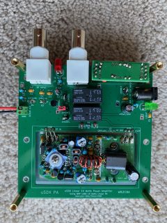
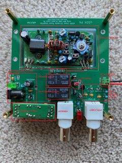
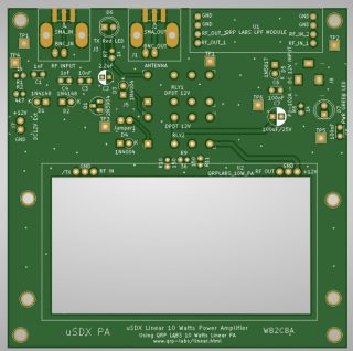
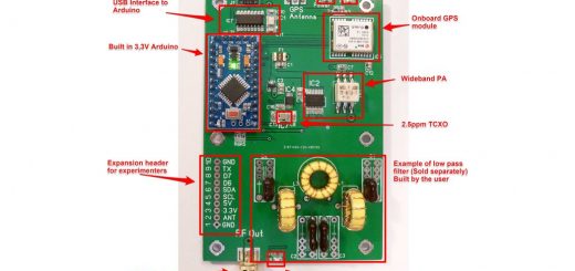
This is the end product: uSDX Linear 10 Watts Power Amplifier Pcb with QRP Labs 10 Watts Linear PA embedded:
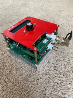
My uSDX PA mated with my uSDX:

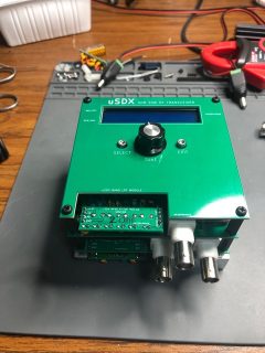
Here is Ken’s uSDX with PA bolted on:
uSDX QRP Labs 10 Watt Linear PA built details:
uSDX PA consists of these building blocks:
– QRP LABS 10 WATTS Linear Power Amplifier:
This can be procured from QRP Labs website. Here is the link:
https://www.qrp-labs.com/linear.html
Hans has an excellent build manual for this kit. Just follow up and build the kit.
– QRP Labs LPF filter:
Low pass Filter for filtering RF output signal. These can be bought from Qrp labs for different bands to operate on. This way uSDX PA will be following the roots of uSDX PCB as Poorman’s Multiband! Just switch the QRP Labs LPF to your desired band to work on.
– 6 db PI Attenuator:
This attenuator has two purpose :
1- To match the input impedance of uSDX which is 50 ohms to higher impedance input of QRP Labs Power amplifier.
2- To lower rf power output of uSDX by a factor of 4.
– PA RF Switching relay and Power relay:
These are two relays to route RF power between antenna, power amplifier and uSDX rf output. On RX, uSDX rf output is connected straight to Antenna input of the PA board. This way signal received by antenna goes straight to uSDX antenna input without any significant loss. Also power to qrp labs PA is off which means that the PA Pcb is consuming no power.
On TX qrp labs PA receives DC 12 Volt and also the rf output is connected to Qrp labs PA rf input and qrplabs LPF is connected to Antenna so that the signal from uSDX is amplified and passed out to low pass filter and then to the antenna.
– DC Barrel Power Connector:
This barrel connector on PA is used to supply the whole rig with DC voltage. Do not use the dc barrel connector on uSDX TRX to supply the PA board with DC power. PA board consumes 2.2 amps on 12 volts. The copper traces on uSDX pcb can not sustain that much power to PA. So it is always a good practice to power the whole uSDX system from PA board DC barrel connector.
– DC to uSDX Connector:
This connector on uSDX PA is used to power uSDX TRX PCB.
– RF Relay switching circuitry:
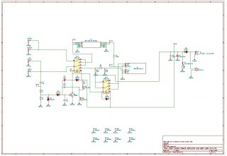
This circuit is used as an rf activated switch which energizes both relays when uSDX begins transmission. When uSDX TRX ends TX, relays switch to RX position automatically.
TX Jumper is used to activate relays without rf input power. This will come handy when adjusting bias of QRP labs PA mosfets.
There are two LEDs. The green one is power LED. When power is applied to PA pcb by DC barrel jack this LED is on. The red LED between two BNC connectors is the TX indicator LED. When uSDX starts transmitting this LED lights on indicating that relays are in TX position.
uSDX 10 Watts Linear PA Schematic and PCB Layout:
Parts and where to order them:
– PCB can be ordered from any pcb house online using the gerber files at the end of this article.
– QRP Labs 10 Watt Linear PA kit can be ordered from this link:
https://www.qrp-labs.com/linear.html
– QRP Labs Low Pass Filter:
QRP Labs sells these low pass filters as kits for each band.
These can be ordered from this link:
https://www.qrp-labs.com/lpfkit.html
– Relays:
I got my relays from Digikey. These are called G5V type relays
https://www.digikey.com/products/en?keywords=z771-nd
– DC Barrel Connector:
This is the same type used on uSDX PCB V1.02.
https://www.digikey.com/product-detail/en/cui-devices/PJ-102A/CP-102A-ND/275425
– BNC Connectors:
https://www.digikey.com/products/en?keywords=arf1690
– Heatsink:
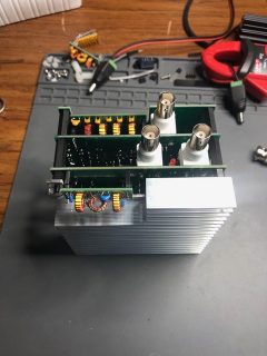
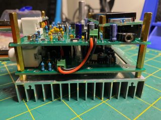
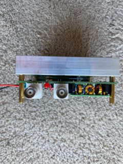
Any flat type heatsink can be used. The important point is that it will be also a carrier for QRP Labs PA which will be bolted on to the heatsink and heatsink will be bolted on to uSDX PA carrier pcb. There are extra 2 mounting holes on each side of the qrplabs PA cut out which can also be used to mount the heatsink.
Ken and I used this heatsink from Amazon. This heatsink has 100 mm x 100 mm size which is ideal for the pcb size:
https://www.amazon.com/Heatsink-100x100x18mm-Aluminum-Radiator-Circuit/dp/B07VCJVS3R/ref=sr_1_9?crid=2WR2BD9J8CAPG&dchild=1&keywords=100×100+aluminum+heatsink&qid=1599953460&sprefix=heatsink+100+%2Caps%2C165&sr=8-9
Same heatsink from EBAY:
https://www.ebay.com/itm/2-Pcs-Aluminium-Radiator-Heatsink-Heat-Sink-Cooling-Fin-100mm-x-100mm-x-18mm/163716867180?hash=item261e49246c:g:EWcAAOSwtYtc9Dq1
Here are some more photos of heatsink and uSDX PCB V1.02:
– PI Attenuator Resistors:
R9, R10 and R11 are all metal film %1 tolerance 1/2 watt resistors.
Rest of the parts are pretty standard.
uSDX PA with QRP Labs PA build steps:
– Mark your heatsink mounting holes for uSDX PA PCB and QRP Labs PA PCB by using qrplabs PA pcb and uSDX PA pcb as marking guide.
Follow these steps:
1- First use the uSDX PA carrier pcb as a marking master and mark 4 corner holes on heatsink. Make sure heatsink bolt holes align on to uSDX PA pcb corner holes.
2- Now align qrplabs PA pcb in the middle of the uSDX Carrier pcb cut out and mark out two IRF510 holes and BS170’s washer hole. Try to align electrical connection pads on QRP Labs PCB as close as can be to similar pads on uSDX PA pcb.
3- Drill all of these holes and check if everything aligns perfect. This part is very important as there is no turning back and easy way to fix things if steps of marking and drilling are skipped. It is hard to align holes with populated pcbs.
– It is a good idea to start with building the QRP Labs 10 W Linear PA kit first. Take your time and build with patience as per qrp labs PA kit manual.
– Install QRP Labs PA on to the heatsink as per the qrp labs PA manual instructions.
– Now build uSDX PA carrier pcb.
– Power up uSDX PA carrier pcb and check if the green led is on. Use a computer jumper to short TX Jumper and observe that both relays are clicking and Red LED is on.
– Bolt on Heatsink to uSDX carrier pcb.
– Solder connections between qrplabs PA pcb and relevant connections of uSDX PA carrier pcb.
– Do not connect any antenna or uSDX to the uSDX PA pcb yet. We need to perform QRP labs PA mosfet bias adjustments first. Power up by applying 12volts power to uSDX PA pcb and short TX Jumper with a computer jumper in place. Now qrp labs PA has power. You can now adjust two bias potentiometers as per the QRP labs PA manual instructions.
uSDX PA connection and testing procedures:
1- Preparing uSDX transceiver RF output level for uSDX PA:
QRP Labs 10 W Linear PA has 26 db gain which means that we need to lower uSDX output sufficient enough to drive the first stage of QRP labs PA without blowing it’s BS170 MOSFETS. We can not apply full power of uSDX which can be 3 watts or more to QRP Labs 10 W PA! This will certainly damage the input stage BS170’s of QRP Labs PA! DO NOT ATTEMPT TO CONNECT uSDX STRAIGHT TO uSDX PA pcb and TRANSMIT without following below steps! DO NOT APPLY more than 200 mw into the uSDX PA!
QRP Labs PA needs an input in the order of 25 miliwatts to max 50 miliwatts. Above that smokes BS170’s at the input of the amplifier. Trust me I know! ? There is 6 db attenuator on uSDX input side which means that we can apply a rf output of max 200 miliwatts to uSDX PA which the attenuator will reduce to 50 miliwatts maximum input to Qrp labs PA.
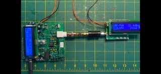
In my uSDX – uSDX PA combination I am applying around 140 miliwatts to uSDX PA input which corresponds to 36 miliwatts rf power in the input side of QRP labs PA which is plenty to work fine.
To prepare uSDX TRX output power to comply with uSDX PA follow these steps:
– Lower PA Bias min and PA Bias max to zero.
– Connect a wattmeter that can measure miliwatts and measure uSDX TX output power.
– Play with PA Bias min and max value to reach a TX RF output value around 140 miliwatts and leave it like that.
– If you can’t lower the TX out below 140 miliwatts then you can always de-solder and remove one of the BS170 PA transistors on uSDX TRX pcb.
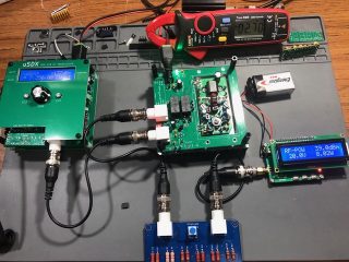
Here is my uSDX TX output set for uSDX PA input:
Now we can mate uSDX TRX with uSDX PA pcb.
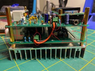
1- Bolt on uSDX PA under uSDX TRX with spacers.
2 – Connect rf output of uSDX TRX to uSDX PA rf input with a short BNC to BNC cable.
3 – Connect uSDX EXT DC 12V 2 pin connector to uSDX PA 2 pin DC 12V connector with two short cables as in the photo. This way we make sure that uSDX TRX gets it’s DC power from uSDX PA pcb, not the other way around. To Apply DC 12 volt to uSDX PA + uSDX TRX we will use uSDX PA pcb’s barrel jack connector.
Powering up the whole uSDX TRX system:
1- Use a power supply of 12 volts which can deliver 3 amps of current. Under 12 Volts uSDX PA works with 2.2 amps in TX.
2- Connect power supply of 12 volts to uSDX PA DC barrel jack.
3- Connect a RF Power meter capable of measuring at least 10 Watts RF power and a dummy load of at least 10 watts to antenna connector of uSDX PA pcb.
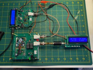
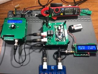
4- Now when you transmit from uSDX you will see a RF power output around 8 to 9 watts on the rf power meter. If that’s the case all is working as expected! and now our uSDX is on steroids! ?
Here are some test photos of uSDX PCB V1.02 with uSDX PA in action:
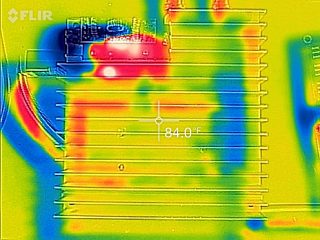
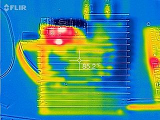
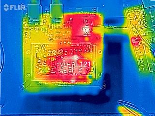
FLIR Infrared Heat Signature Images of heatsink after 3 minutes of continous TX:
Testing uSDX Transceiver with uSDX PA in the mountain!
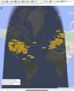
This is my first FT8 qso attempt with uSDX 8 watts RF output with uSDX battery pack as a self contained battery powered SOTA Rig.
For the first time I could reach majority of Europe and USA with uSDX in digital modes which is pretty good.
Final Note:
This uSDX Linear 10 WATTS PA is compatible with WB2CBA uSDX PCB V1.01 and PCB V1.02 mechanically to bolt on.
This 10 Watt Linear PA design is not limited only to use with uSDX TRX. It can be used with any qrp ham radio rig that has rf output less than or equal to 200 miliwatts.
I hope this PA will bring more qso’s and joy to all uSDX users.
I would like thank Ken Delap, KX9U for his endless tests and support on this project and also for his fine craftsmenship on the PA Heatsink.
Happy builds and enjoy!
Barbaros Asuroglu aka Barb, WB2CBA
09/12/2020 NY, U.S.A.
FILES:
GERBER_uSDX_QRPLABS_PA
uSDX QRP LABS PA Schematic
WB2CBA uSDX PA _10 Watts Power Amplifier KiCAD Files
————
– This pcb design can not be used commercially without the consent of Barbaros Asuroglu WB2CBA.

