ESP WSPR – Simple and Inexpensive WSPR Transmitter
ESP WSPR – A Simple and Inexpensive WSPR Transmitter Implemented with ESP8266 and SI5351
- In my article “ A Whisper Adventure… ”, I tried to tell you about my adventure with WSPR and how I put the ESP_WSPR transmitter together, programmed it, and tried it.
In this article, I will try to convey the information you need to make your own ESP_WSPR, WSPR transmitters.
ESP_WSPR is an inexpensive and simple transmitter that combines modules using Espressif’s ESP8266EX IC and Silicon labs’ SI5351A IC and broadcasts using the WSPR – Weak Signal Propagation Protocol.
ESP8266EX is a module produced by Espressif company with all wifi protocol and ARM processor.
https://www.espressif.com/en/products/hardware/esp8266ex/overview
With this module, you can connect to your WIFI router and communicate over the internet.
SI5351A is a Digital Controlled PLL Integration produced by Silicon Labs. PLL (Phase Locked Loop) can be roughly translated into Turkish as a phase locked loop. The SI5351A generates a PLL controlled square wave signal from its three outputs, providing frequency control between 8khz and 160 MHz with a resolution of hertz. The main purpose of this IC is to produce different clock frequencies needed in computer systems with a Crystal oscillator.
The SI5351A is a very popular IC among amateur radio operators and is often used as a VFO-variable frequency oscillator.
https://www.silabs.com/documents/public/data-sheets/Si5351-B.pdf
Let’s start by examining the ESPWSPR schema:
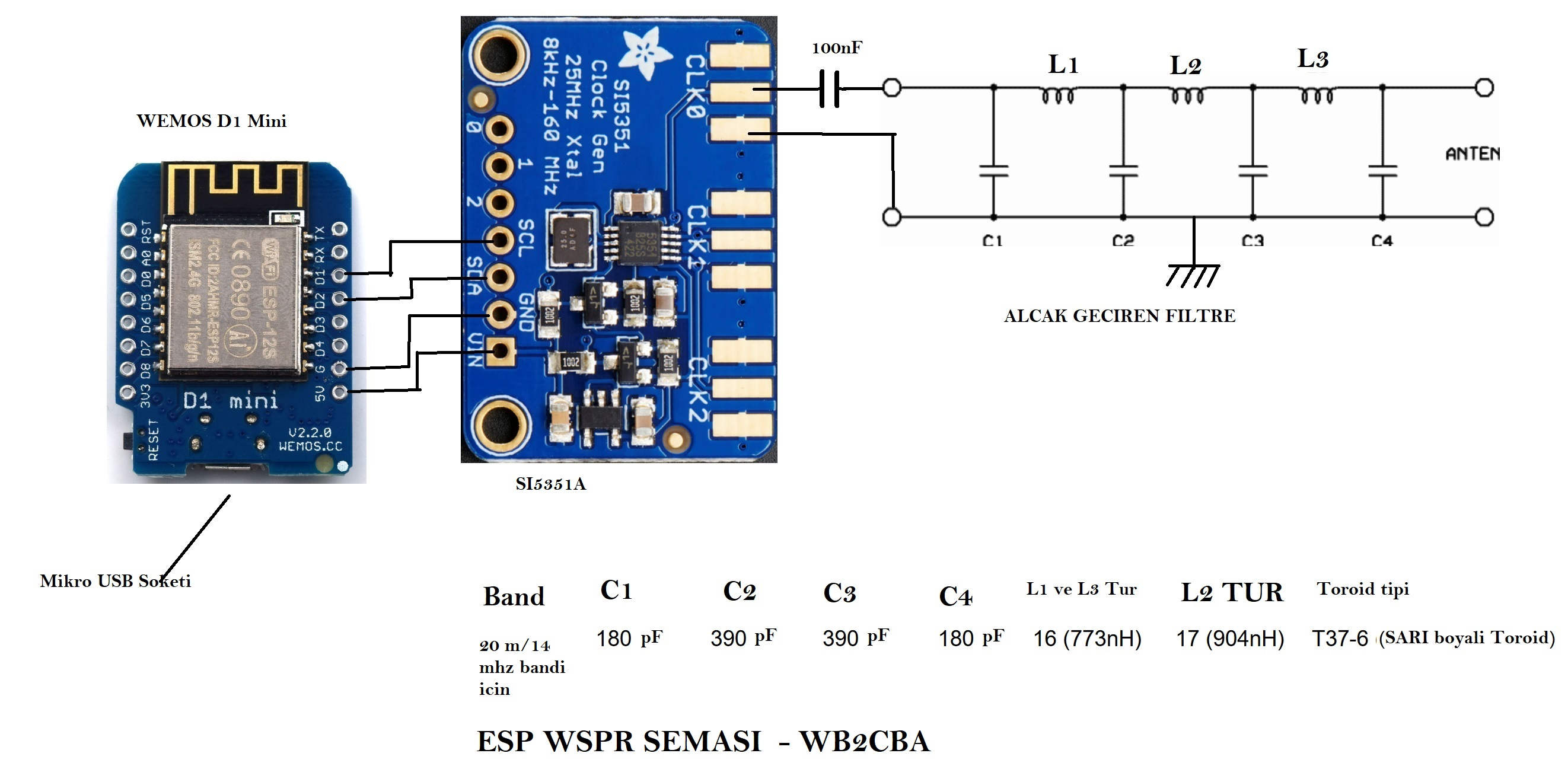
ESPWSPR consists of three main modules or sections.
- WEMOS D1 mini ESP8266 module
- SI5351 module
- low pass filter
I had the WEMOS D1 mini module for the ESP8266 and I used it. WEMOS D1 mini module can be obtained from www.aliexpress.com or in Turkey from www.direnc.net and www.N11.com . Any ESP8266 NODEMCU module can also be used.
The SI5351A module is available at www.aliexpress.com . It can also be obtained from www.direnc.net and www.N11.com sites in Turkey . The price is about 5 dollars.
The SI5351A output is square wave and produces a lot of harmonics when you give it directly to the antenna. A 7-point low-pass filter is used at the SI5351 output to prevent this and convert the output signal from a square wave to a clean sine signal.
For the low pass filter, I used the values from the QRP Labs site for 14 mhz.
https://www.qrp-labs.com/lpfkit.html
Interestingly, QRP Labs is a British amateur radio operator living in Muğla Dalyan, Turkey. It sells filter kits for $4.60. If it’s easier for you, you can order from there.
I chose the 20 meters/14 Mhz band. I chose this because the antenna size is relatively smaller, but the propagation conditions are better compared to higher frequency bands. In this explanation, I will take the 14mhz/20 meter band as a basis.
If desired, ESP_WSPR can work in all bands up to 144 MHz by using filters in other bands and changing the frequency value in the software.
ESP_WSPR nominal RF output power is 10 milliwatts under 50 ohm load.
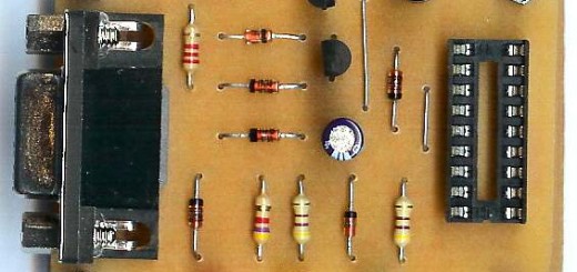
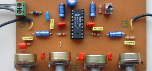
Since the circuit is quite simple, it can be installed in a perforated perpendicular without the need for a printed circuit.
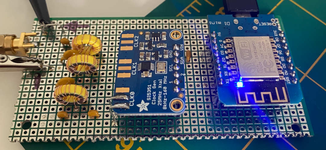
The circuit mounted on the perforated axis is in a very simple and small form as in the picture.
Toroidal coils for the low-pass filter are type T37-6 from AMIDON. L1 and L3 coils are 16 turns of 0.30 mm wire. The L2 coil is 17 turns of 0.30 mm wire.
Toroid details are in the link below:
http://www.amidoncorp.com/t37-6/
SOFTWARE:
Before programming the ESP_WSPR program with Arduino, we need to take a few steps.
Although it is simple to realize this, it makes things very easy if you are familiar with the Arduino environment. There is a mock site and documentation on the Internet about Arduino. If you have never dealt with Arduino, I recommend that you deal with Arduino before attempting ESP_WSPR. Otherwise, you will have to deal with lots of sleepless nights and error messages.
I have avoided giving detailed information about these processes in this article. Otherwise, our article becomes quite long and complex. Instead, it made more sense to support this article with links that describe these processes in detail.
- The first step is to download the Arduino IDE program and install it on your computer.
https://www.arduino.cc/en/Main/Software
You can download and install it from the Arduino site.
- The second step is to introduce the module boards with ESP8266 processor to the Arduino IDE program you have installed.
https://randomnerdtutorials.com/how-to-install-esp8266-board-arduino-ide/
This site tells you how to do this process, both visually and with explanations.
- Libraries: ESP_WSPR makes use of several modules and function libraries.
As I mentioned in my previous article, these libraries are amateur radio operators, and this is software prepared by devoted people and given to the Arduino world as a gift. We amateur radio operators and practitioners use these libraries in our programs in the most appropriate way for our work. Of course, this means a terrible labor and time gain for us.
In order to use these ready-made libraries, you must first introduce them to the Arduino software.
The link below tells you in detail how to do this.
https://www.arduino.cc/en/guide/libraries
I will put the zip files of all the necessary libraries together with the ESP_WSPR program at the end of the article, but I also give the links below in case you want to download the latest versions.
ESP_WSPR uses the following Libraries:
SI5351 – Required library to use this SI5351 module. I used the NT7S library written by Jason Mildrum for this.
https://github.com/etherkit/Si5351Arduino
Wire – A library available in Arduino. You don’t need to install.
JTEncode – This is one of the most important libraries. Its purpose is to create the necessary data for the wspr protocol, make it ready for sending and store it. In this library, the NT7S was written by Jason Mildrum.
https://github.com/etherkit/JTEncode
int – int You don’t need to load a library in Arduino.
NTPtimeESP – NTPtimeESP Network Time Protocol library that provides time synchronization with servers.
https://github.com/SensorsIot/NTPtimeESP
TimeLib – Library that provides time control.
https://github.com/PaulStoffregen/Time
ESP8266WIFI and WIFIClient Libraries that allow the ESP8266 to connect to the Internet and access data. Since these libraries are automatically uploaded to Arduino when you introduce the ESP8266 module, they do not need to be loaded separately.
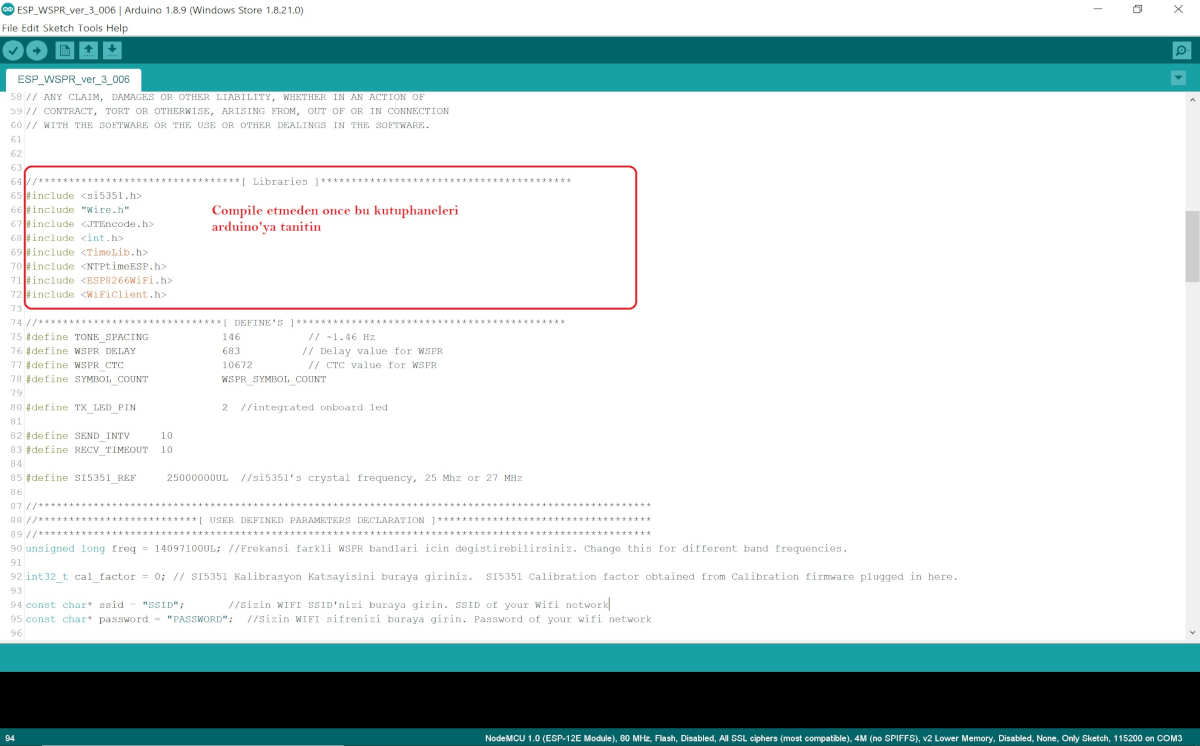
(Image ESP_WSPR libraries)
ESP8266 Board Selection:
Select NodeMCU 1.0(ESP12-E Module) by clicking Board from the Tools section in Arduino.
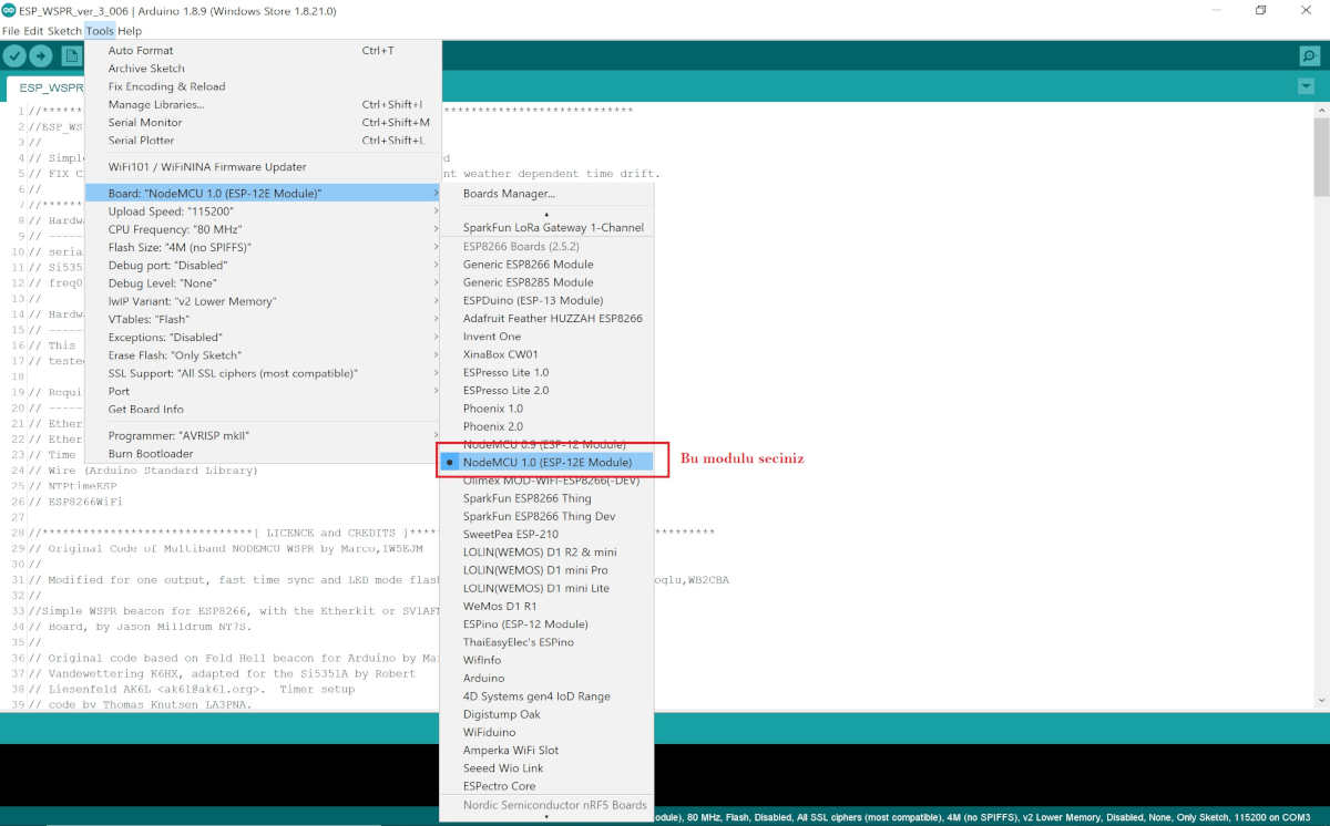
(Image: ESP board selection)
- Now at this point, connect your WEMOS D1 Mini or similar module to your PC via USB.
Now we can select the Serial communication port. Select the appropriate Com port by typing Port in the Gene tools menu. You should see the com port you selected in the lower right corner of the Arduino IDE screen. This will allow you to send a program to the ESP8266. At the same time, you will be able to monitor the operation of the circuit using the Serial Monitor screen under Tools and the baud rate of the relevant program.
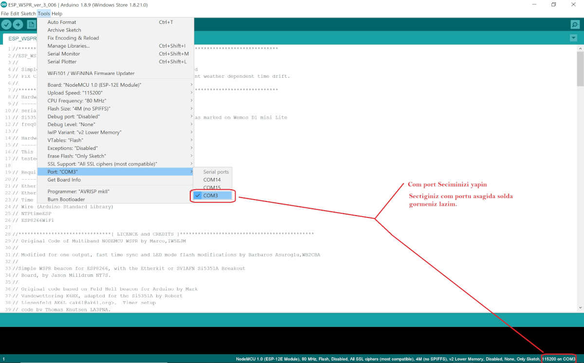
(Image: Serial com port selection)
So far, we have prepared and installed the Arduino IDE program for ESP_WSPR and ESP8266.
At this point, it’s time to test if the ESP_WSPR you installed and mounted your first program is working.
For this, you will need an oscilloscope with at least 25 MHz bandwidth and a sensitive at least 25 MHz frequency meter. The oscilloscope is needed to see how clean the signal is, to see the WSPR frequency on the frequency meter and to set the SI5351 calibration. If you have a simple 50 ohm artificial load, you are ready for the tests!
First Test:
For this, short-circuit the output of the low-pass filter of the circuit you have set up with a 50 ohm load. Then connect this output to oscilloscope and frequency meter in parallel.
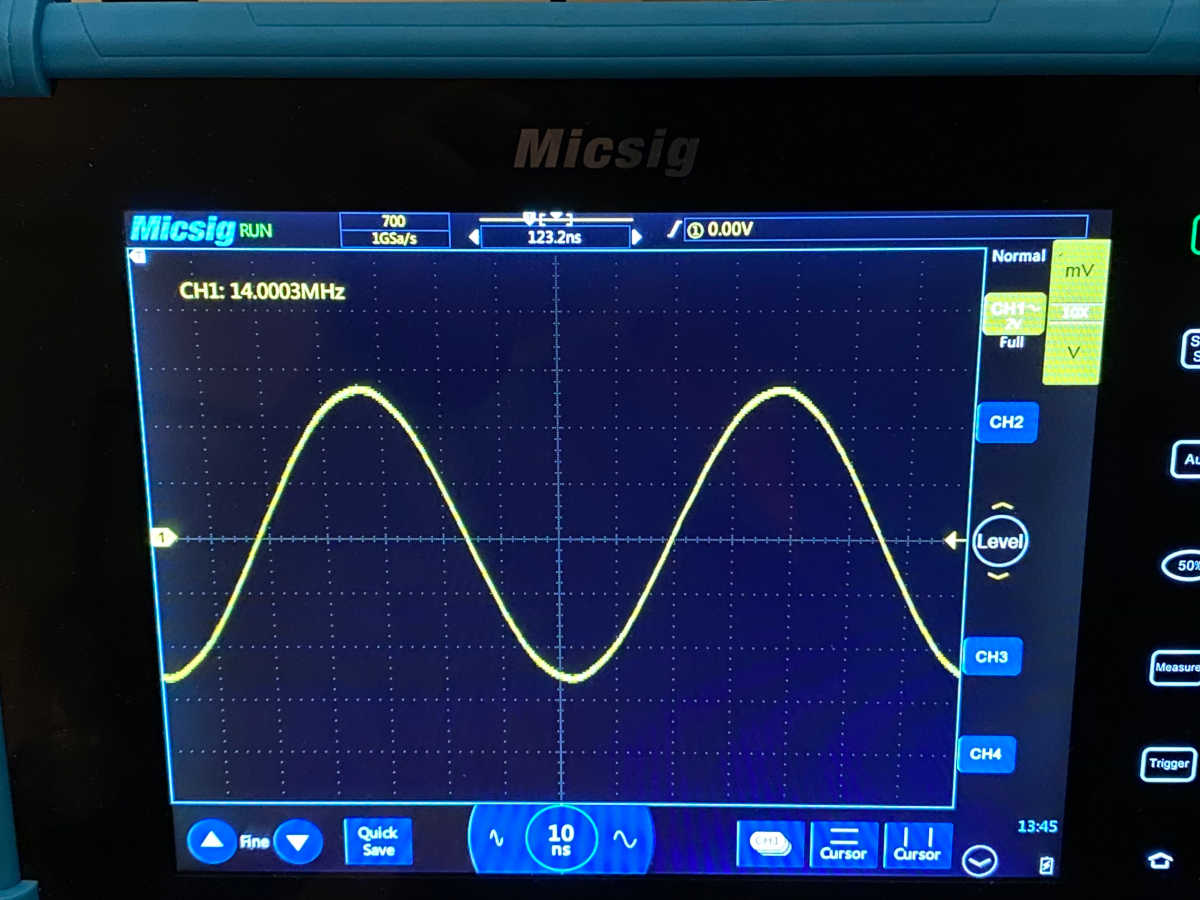
Then upload the ESP_WSPR_SINUS_URETECI.ino file from the attached zip file to Arduino and program the ESP8266. When you run it, you should see a clean sinus signal close to 14.000.000 MHz. If you can see this, the circuit you made has passed the class! It is very normal that you do not see exactly 14,000,000 mhz.
When I first turned it on, I saw that the output signal was off.
You should see a sine wave like the one below on your oscilloscope. As you can see, my signal is 14.000300 mhz, ie 300 hz. Now we will calibrate this boat to be exactly 14.000000 Mhz.
(image: 14.000.03 mhz scope)
SI5351 Frequency Calibration:
Among the examples in the SI5351 arduino library there is a great program for calibration (measurement). Using it, you will set the calibration value to be exactly 14.000.000 Mhz and write it down. You have to do this once for each SI5351 module on the first run. The reason is that the value of the oscillator crystal used is different for each module and there is a calibration constant in SI5351 to compensate for this difference. We will note this down and use it in the esp_wspr program.
I changed the calibration program a little bit. Use it if you want. File named SI5351_FREKANS_KALIBRASYON.ino in the attached zip file. When you open this file with Arduino and program it into the ESP8266 it allows you to calibrate your output signal.
To do this, run the serial monitor application inside the Arduino. The esp8266 must be connected to the usb port and the correct port must be selected before running Serial Monitor.
Set the serial monitor baud rate to 115200 pbs and briefly press the reset button on the WEMOS D1 mini.
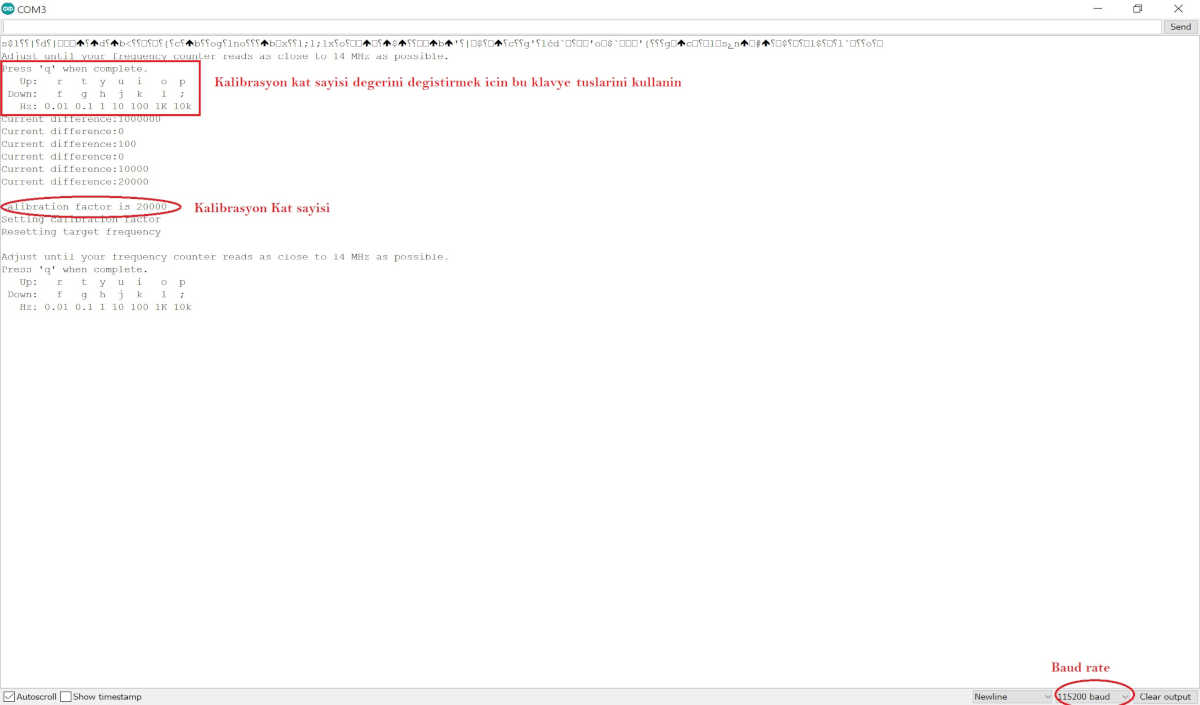
You should see the following screen:
(image: calibration screen)
Connect the antenna output of the circuit to a dummy load. Connect to your oscilloscope and frequency meter at the same time.
By the way, if you haven’t installed the low-pass filter yet, don’t worry, connect the SI5351 first output directly to an Oscilloscope and frequency meter and observe the signal frequency. Instead of a sine, you will see an output signal close to a square wave.
Try to set the frequency to be exactly 14.000.000 mhz by playing with the keyboard keys indicated with up and down on the screen.
P and ; keys increase or decrease the frequency by 10 kHz. The r and f keys increase or decrease 0.01 Hz. It allows you to increase the frequency as shown on the screen in other keys.
The aim is to reach 14,000,000 MHz as much as possible with these keys.
Let’s say you see exactly 14,000,000 mhz on a frequency meter or oscilloscope (most modern digital oscilloscopes today have a precise frequency measurement function).
The frequency is exactly 14 MHz and you are satisfied with this result, then press the q key. Make a note of the number in the section that says Calibration factor is 20000. I chose 20000 as an example, yours will be a completely different number depending on your setting. This number you noted is your calibration coefficient for your Si5351 module. This number will compensate for the SI5351 crystal deviation and produce the true frequency.
ESP_WSPR Software:
We are now ready to install the ESP_WSPR software.
Download the program named ESP_WSPR_ver_3_006.ino from the attached zip file to Arduino IDE.
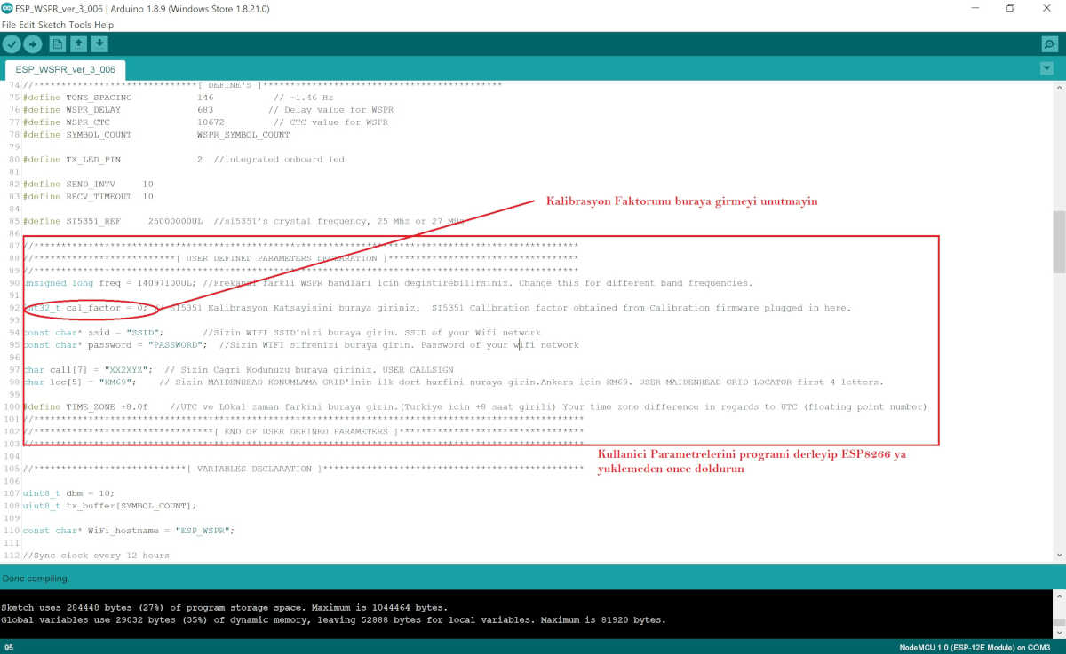
At this point, we will enter the calibration coefficient, WIFI SSID and password and user information into the program. You will do this only once. This information will be saved in the ESP8266 during programming.
(image: ESP_WSPR_3.006 user parameters)
Enter the calibration coefficient you noted earlier into cal_factor as seen on the screen above. This will now allow you to output without frequency drift.
Likewise, instead of SSID, enter your own wifi router SSID and your WIFI password under it and your own call code instead of call. Do not forget that you will be among them ” “! Delete the zero and enter the calibration coefficient where it is 0.
In the Loc section, you will enter the first four letters of your Maidenhead Grid locator location.
You can get maiden head grid locator information from this site: https://dxcluster.ha8tks.hu/hamgeocoding/
Before programming, connect the antenna output of the circuit to a dummy load.
Now compile your program and program the ESP8266.
We are ready to try ESP_WSPR.
Connect the antenna output of the circuit to a dummy load. Connect to your oscilloscope and frequency meter at the same time.
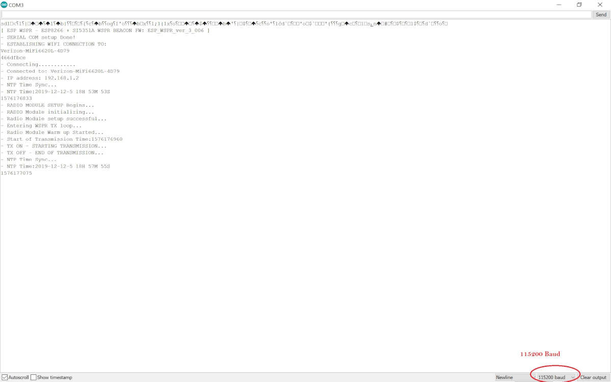
Open Serial Monitor under Tools and select 115200 baud. Briefly press the reset button on the ESP8266 module.
It starts working with a screen like below ESP_WSPR.
Meanwhile, the blue led on the ESP8266 module starts blinking at short intervals, indicating that it is trying to connect to your WIFI network. Blue LED turns off when WIFI connection is established. If the blue led continues to flash for a long time, there is a problem with your WIFI connection and the circuit cannot be connected. Check the WIFI SSID and PASSWORD you entered in your program. Did you enter correctly?
(image: ESP_WSPR TX screen)
After the WIFI connection is established, ESP_WSPR provides time synchronization with the NTP server. The blue led flashes for a short time at any time of synchronization.
Then the SI5351 module is prepared to send the wspr data. ESP_WSPR starts waiting for full dual time clock minute to start sending. When it starts sending, the blue led lights up and stays on until the sending process is finished. This process takes 110 seconds. It provides thermal stability of the circuit by sending the transmitter fixed carrier 30 seconds before the sending led turns on. You can follow the signal from the oslioscope and frequency meter during the transmission.
After this process, the circuit contacts the NTP server again and provides a new time synchronization over wifi. While doing this, the blue led flashes briefly.
ESP_WSPR goes to sleep for 4 minutes. After four minutes, ESP_WSPR wakes up and starts sending a new WSPR data. The process continues like this.
If the blue led stays on continuously during the NTP server connection, there is a slowdown or problem on the wifi. Press the ESP8266 reset button briefly to reset the system. If the problem persists, check your wifi system. It means there is a connection problem.
I tried to tell you how to make ESP_WSPR, a cheap and simple WSPR transmitter. I hope you make this circuit and add your own callsign among the WSPR SPOTs.
You can find all the libraries I mentioned here and all the software related to SI5351 and ESP_WSPR in the ESPWSPR software file.
Conclusion:
Working with ESP_WSPR and Weak Signal Propagation Reporter in general – WSPR has given me immense pleasure. I hope you will feel the same excitement as I did when you see your first signal reach thousands of kilometers away with a ridiculous strength.
I would like to thank my friends K1FM Alain DeCoralis and KD2RCP Çağlar Akgüngör who supported me with knowledge and helped me with my trials. Thanks to them, I learned a lot about WSPR and antennas.
I am also indebted to IW5EJM Marco, who laid the foundation for the wspr program with the ESP8266. If it weren’t for his schedule, there would be more sleepless nights.
I respect the whole open source software and Arduino community. It would not be possible to write such articles without the open source philosophy.
Stay with love,
Barbaros Asuroglu, WB2CBA, New York, 12/17/2019

