FDIM 2024 LOGIC IC TRANSMITTER CHALLENGE
A Brief Background History About My Entry Circuit and My Surprise Win!
It all started on early March 2024 with a phone conversation with my friend TA1MHS Muhsin Dogrular. He asked me if I am going to visit Dayton Hamvention this year. I told him that I will visit both FDIM and Hamvention. He suggested that I should look into FDIM 2024 LOGIC IC CHALLENGE!
I didn’t pay much attention to that challenge at the beginning. Then I checked the rules and I decided to give it a go as I already did most of the leg work past couple of years.
For almost a year I am into QRPp TTL powered digital modes transceiver designs. These transceivers are TTL IC powered sub 500mW rigs which I use extensively for portable FT8 and FT4 SOTA/POTA/Hiking/Backpacking activities. I am pretty familiar with logic IC transmitters due to these rigs which convinced me to participate in this year’s FDIM LOGIC IC challenge. It was now a matter of increasing power of my TTL Transmitter.
In my designs I use an advanced TTL octal buffer, 74ACT244 which is my favorite. With this buffer IC I can get 500mW on 7 mhz under 5V with my portable rig design.
FDIM 2024 LOGIC IC challenge rule was to use a 7.030 mhz crystal and one LOGIC IC chip 7400/4000 series with as much as passive components you like, such as resistors, capacitors and inductors. The most important rule is, there can be only one active element, the logic IC!
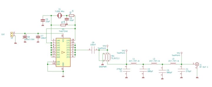
After some breadboarding and testing I came up with this basic schematic:
My Logic IC PA HF rig designs are using SI5351 as oscillator. In FDIM Challenge a crystal should be used. This meant I can’t use my go to IC 74ACT244 as it is a non-inverting part. So I switched to 74ACT240 which is the twin sister of 74ACT244 but as an inverting part.
Why I need inverting logic? To create a crystal oscillator with one gate I need an inverting gate to feedback oscillation signal. So I used one of the eight gates of 74ACT240 as the oscillating gate.
Now as I had a stable 7.030 Mhz nice square wave signal coming out of the first inverting buffer gate, I parallel rest of the buffers and applied that square wave oscillation to the input of those buffers in parallel.
I also parallel those 7 buffer outputs to increase FAN OUT of the chip to drive a transformer. I still have a square wave and a DC component to it. Adding a 100nF capacitor at the output of those buffers I have now an AC signal that I can feed into my bifilar transformer to step up my pulse voltage.
While back in march 2020 when we all were quarantined due to COVID 19 I did experiment quite a deal with standalone WSPR transmitters using TTL chips as PA chips with hand wound bifilar transformers to boost output waveform of TTL PA. Under 5 Volts with only one 74ACT244 TTL chip I could go up to 300mW under 5V DC supply with my hand wound FT37-43 bifilar transformers.
I noticed at that time after winding many of these transformers and testing them in my test transmitter circuit I could never get the same amount of power output of them as a standard. There is always a power difference from one bifilar toroid to the other one no matter how careful and tedious I am winding them.
Back In 2020, this really annoyed me. I needed something that is a standard part bifilar transformer that gives an optimum constant non-varying performance.
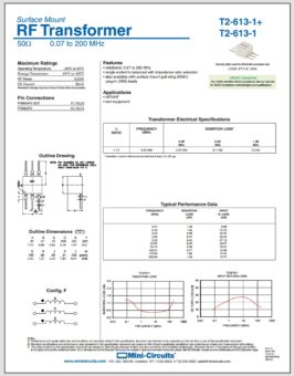
After searching online for days for all kinds of ready wound bifilar and trifilar transformers and ordering them and then testing them etc. I settled on one! MINICIRCUITS T2-613-1!
www.minicircuits.com is a New York based RF components company specializing in RF products.
T2-613-1 is 0.07 – 200 Mhz trifilar high performance RF transformer handling RF power of 250 mW.
When I saw quarter of a watt my first thought was bummer! I wanted to output more than that!
I said you know what, let me give it a try and see what is the make or brake point of this little guy! 😊
I was surprised to see that it works up to 2 watts RF power like a champ! From that moment on I never looked back and this little transformer is my go to solution in all my TTL PA QRPp rigs.
Come back to FDIM 2024 LOGIC IC CHALLENGE entry, this was a no brainer! I used that minicircuits transformer again.
Ok now I have my generated and stepped up 7.030 Mhz oscillation though it is a nasty jumble of kind of a square wave signal with lots of harmonics. I could have left it like this and take it to FDIM test bench as they will connect a bandpass filter which will filter all harmonics and create a nice sine wave right? Well my conscious said otherwise and I couldn’t leave it as it is all over the place signal and entered it to a 7 pole, 7 Mhz LPF filter which gave a nice 7 mhz Sinus signal with -58dbm 2nd harmonic! Though I lost a bit power which might be a huge difference in a power output competition but I was sure at least that I am not generating a jumble of harmonics!
After verifying the schematic, I put together a Manhattan style board to test all. It worked!
Now the date was end of March 2024 and I had a working schematic and a crude prototype ready to pack and go for the competition!
Something was nagging me! Timewise I still had 2 months almost and my prototype looked primitive and ready to fall apart!
So I decided to design a PCB version of my entry circuit and not any PCB version, a SMD manufactured PCB version! 😊
After designing, checking sending to www.jlcpcb.com in China and getting back fabricated PCBs was the next step.
The end result is this:
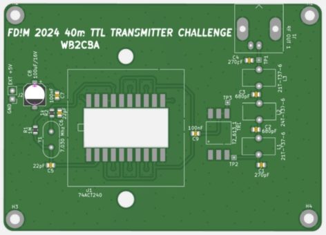
This is the DFM Footprint placement analysis layout of my PCB design
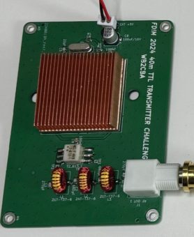
And this is final product:
AS can be seen on DFM analysis PCB photo I spread the pins of 74ACT240 so that I can lower the profile of chip as much as I can. The reason being ease of copper heatsink installation. My other thought was I can sandwich the 74ACT240 chip between two identical copper heatsinks if needed.
I used a PC processor copper heatsink which I got from amazon for $5.
Tests and Durability Analysis – In more crude words: Pushing limits until smoke!
After building two pcb prototypes with the new smd PCB boards I started the fun part! Powering up and pushing it to find the make or brake limit!
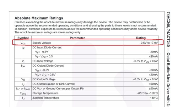
Here is a screenshot from 74ACT240 Datasheet on Maximum Permissible Operating Limits:
I continued testing both prototypes with these test conditions and criteria:
- Total test power on run will be 10 minutes under each voltage condition. There will be 30 minute cool down period between each run to dissipate heat and start over with an ambient temperature heatsink temperature every time.
- I will use the same power supply, same 50 ohm dummy load and same rf power meter and scope for all tests.
- I am not going to measure heat dissipation but will have a simple criterion, if the heatsink burns my finger, then it will be considered HOT! I will be using one heatsink initially.
- Efficiency will be calculated by dividing RF power with DC input power times 100 as percentage.
I let the fun begin and started testing:
- I powered up first within spec nominal condition voltage of +5 Volts. RF power output was 520 mW. No noticeable heat dissipation. Efficiency:87%
- Then I tried 6Volts. RF Output = 742 mW. No significant heat dissipation. Efficiency:82%
- 7 Volts, RF Output = 1021 mW. No significant heat dissipation. Efficiency:78%
So up to 7V I am still in 74ACT240 Maximum limits boundary and not exceeded. - 8 Volts, RF Output = 1.38 Watts. Slight heat dissipation. Efficiency:70%
Now we are on uncharted territory! Anything can happen. - 9 Volts, RF output = 1.656 Watts. No significant heat dissipation. I can easily hold the heatsink after 10 minutes of run. Efficiency:58%
- 10 Volts, RF Output = 1.80 Watts. Still not a significant heat dissipation after 10 minutes. I can still touch the heatsink comfortably. Efficiency: 49%
- 11 Volts, RF Output = 1.99 Watts. Now something strange happened!
Suddenly heat dissipation increased and efficiency of circuit dropped dramatically. In all above tests efficiency, which is RF output power divided by DC input power was above 50%. In 11V case efficiency dropped to 30% which means that my circuit was generating 30% useful power and 70% heat which is not good. Though it didn’t fail even after 10 minutes of continues transmission which was a good sign though not reliable for a competition entry.
12 Volts, RF Output = 2.4 watts. Now this was impressive! I broke the 2 watt barrier but with a catch for only 30 seconds before seeing the infamous smoke which is not enough to win FDIM logic IC competition as one of the main rule is to TX for 60 seconds two times in a row. 30 seconds won’t cut it.
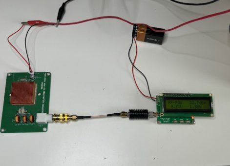
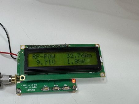
After these make or brake tests I found my sweet spot magical DC Voltage: 10.4 Volts and 1.88 Watts on my RF measuring setup.
How did I come to choose this magic number! Couple of criteria played important role on this:
Efficiency: I limit the efficiency to 43% which is significantly better than 30% of 11V and for a sacrifice of 100 mW over reliability I’ll take it.
Heat dissipation after 10minutes of continues TX was negligible which is a very good sign.
Here are two photos of my test setup and power measurements under this 10.4 Volts magic number:
I didn’t stop testing here. I wanted to have a reliable high power setup so I did the ultimate insane test before packing to FDIM! 24 hour run! 😊
Passed with flying colors and ready to compete!
FDIM 2024 – 05/17/2024 around 1900 hours:
I arrived to FDIM 2024 venue at Holiday Inn Hotel around 19:00 and I was really nervous. I never attended a challenge before, especially an electronics challenge as this one!
I met David Cripe, NM0S for the first time in person. I exchanged emails with him but no eyeball QSO before this meeting. I like his designs and especially the 4State QRP tuner.
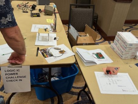
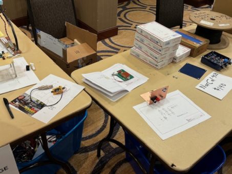
I checked in for Logic IC transmitter challenge and placed my setup on entries display table.
Now there was nothing I can do other than hope for the best and wait my turn to demonstrate! 😊
There were 16 entries in the list and my thought process was no way I can beat 15 hams! I am sure there is a much better design out there. Well at least it will be fun to participate!
In these kinds of challenging events my motto is to wait till the end rather than going in first and get over with it. This gives me time to calm down and gather thoughts and confidence. This is exactly what happened and I was one of the last contestants.
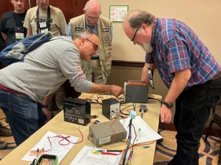
Here are couple of photos of my first and second, “60 second run” while setting up my Logic IC transmitter in front of David Cripe, NM0S. I am the one on the left.
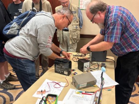
After two runs of 60 seconds at 1.8 Watts I was relieved at least my board didn’t smoke in the middle of these runs. David recorded my output as official 1.8 Watts and I was in great relief though I still wasn’t sure who officially won the challenge. I knew I did perform better than I expected but I was still unsure.
Hans Summers from QRP LABS was watching my transmitter performance and his comment made me laugh, “Well done Barb, watch yourself, next year I am coming after you!” 😊
FDIM 2024 – 05/18/2024 around 2100 hours!
Saturday, May 18th I attended FDIM Annual Banquet at FDIM 2024 venue at Holiday Inn Hotel, Dayton, OHIO.
It was a great event and great night! I sat on a table with an old friend of mine and Hans Summers from QRPLABS and 6 more hams. We had a great time and a great eyeball QSO. The food served was excellent as always.
Around 21:00 hour David Cripe, NM0S took to stage and started to announce the winners of various competitions of FDIM 2024 event.
When it was time to announce The Logic IC Transmitter Challenge Winner, I was holding my breath!
When he announced my name and callsign as the winner of FDIM 2024 Logic IC Transmitter Challenge my heart was pounding like crazy! I never expected that moment will be a reality and here I was. I was the winner among 16 participants. All that breadboarding, PCB designing and going one step further, getting crazy as my friends called me by getting manufactured a dedicated SMD PCB for a onetime event and extensive testing! All paid off, it was a great relief.
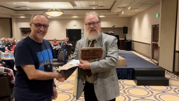
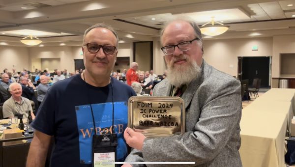
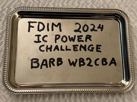
Here are some photos of me collecting my winner certificate and Traditional Dollar Tree Trophy presented by David Cripe, NM0S.
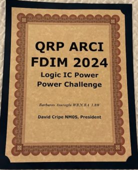
Here are photos of my Certificate and My Dollar Tree Trophy!
I will never forget FDIM 2024 and that night I received my trophy. A small step for humanity but a big step for Barb! 😊
I would like to take this opportunity to thank FDIM 2024 organizers and David Cripe, NM0S for putting together such a fun event. This is the beauty of our hobby called Ham radio!
Barb, WB2CBA
NY 05/29/2024

