Poor Man’s HF SSB Receiver-Let’s Build It
Poorman’s HF RX – A simple HF Digital Modes Receiver – Let’s Build it!
In the first part of this article series I tried to put together the reasoning behind this project and how it works and what it is for in simple terms.
In this article we will dig into the practical side of things and building the HF RX.
As we talked about in the first part of this article series this HF receiver is aimed only to receive so called digital modes of HF band and specifically the 20 m/14 mhz band. This doesn’t mean that it can’t be used for other bands. Actually this receiver can be used on all HF bands simply by switching the input filter to suitable band filters and modifying the vfo frequency to suit the chosen band parameters.

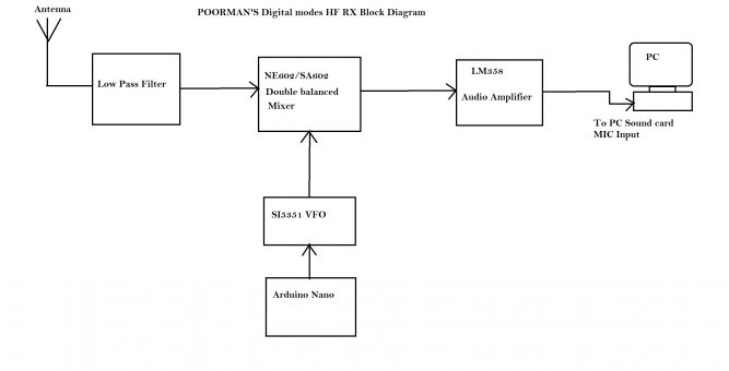
HF Digital Modes Receiver consist of five main blocks.
1- Low Pass Filter – This is the filter to suppress anything above 20m/14 mhz.
2- Double Balanced Mixer – Which is basically consist of NE602/SA602 double balanced mixer IC.
3- Audio Amplifier – LM 358 opamp is used to amplify audio signals suitable for PC soundcard MIC input.
4- PLL Synthesized VFO – This is a SI5351A PLL synthesized VFO module responsible for generating necessary frequencies.
5- VFO Microcontroller – This is an Arduino Nano Microcontroller which is responsible to control SI5351A to select and generate all four digital mode receive frequencies.
This HF receiver is the simplest form of receiver which is a direct conversion type receiver. Audio is produced by mixing VFO frequency with the input frequency from the antenna and low pass filter in the mixer and the output is pure audio which is amplified by the operational amplifier.
When we look at the internal structure of NE602/SA602:
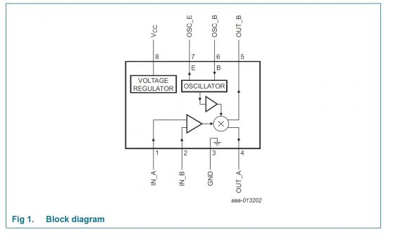
– There is an internal oscillator with a buffer which is injected to a mixer.
– There is an amplifier with two inputs used to inject signal to the mixer.
– Dual outputs from the mixer.
This structure allows user to design a receiver and a transmitter with one IC. In this receiver only taking the advantage of using it as a receiver. So in this scheme the oscillator is external which is the VFO and the internal oscillator is not used. Instead the internal buffer is used. Signal from the low pass filter is injected to IN_A then amplified before reaching the mixer input. Then taking the mixed signal from mixer output OUT_B and amplify it with an opamp.
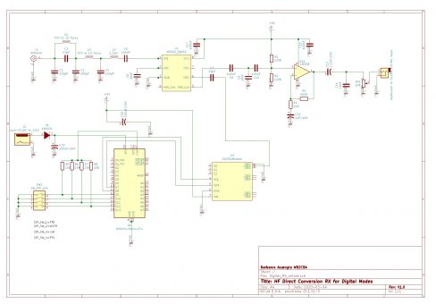
HF RX Schematic:

This is the schematic of the HF Rx digital Mode Receiver. You can spot all of the modules we described above in this schematic.
Before explaining the Arduino and Software side of things let’s clarify couple of practical points:
4 DIP Switches are used to select the VFO frequency for each Digital weak signal mode.
As I mentioned above this receiver is set to receive on 20m/14mhz band and the Arduino software is set to four digital mode frequencies which are FT-8:14.074 Mhz, WSPR:14,095.6 Mhz, JS-8: 14.078 Mhz and FT-4: 14.080 Mhz.
I chose these fixed frequencies as these are the most popular modes. The software can be modified for other mode frequencies such JT-65 or JT-9 etc. by plugging in the appropriate corresponding frequencies.
DIP Switch 1 corresponds to FT-8
DIP Switch 2 corresponds to WSPR
DIP Switch 3 Corresponds to JS-8
DIP Switch 4 Corresponds to FT-4
To choose a mode frequency only push that DIP switch to ON position and leave the rest as OFF.
The inductors L1 and L2 are wound on an Amidon T37-6 yellow toroid, L1 = 15 turns and L2 = 13 turns from 0.35 mm enamel copper wire which corresponds roughly to 28 AWG.
L3 is a resistor shaped 2.2 uH fixed rf inductor which can be purchased from aliexpress.com or ebay.com. as an example:
https://www.aliexpress.com/item/32811389798.html?spm=a2g0o.productlist.0.0.4c3e226eKhfLur&algo_pvid=d209acf9-7d31-4e3b-abae-96055c1d3011&algo_expid=d209acf9-7d31-4e3b-abae-96055c1d3011-2&btsid=0ab6d67915838537542487091e5311&ws_ab_test=searchweb0_0,searchweb201602_,searchweb201603_
Arduino has a regulator on the board to convert any voltage between 6V and 12V at VIN to 5 Volt. You either choose to power the circuit from the DC jack input between 6 V to 12 V voltage or you can equally power from the Arduino USB input with a USB cable. Only 5 volt is needed to power the circuit.
The 10 K trimpot is audio level gain and it should be adjusted not to overload the MIC input of the soundcard.
For FT modes and WSPR mode we will use WSJT/X software which can be downloaded from:
https://physics.princeton.edu/pulsar/k1jt/
and for JS-8 you can download the JS8Call software from this link:
http://js8call.com/
Both of these programs have a Decibel input indicator which will help you to adjust the Audio Level gain with the help of the 10 k trimpot. You shouldn’t exceed 50 to 60 db and certainly not pass to red line limit for a healthy receive.
Arduino VFO Software programming Tips:
SI5351 VFO is controlled by Arduino Nano microcontroller board. I chose Arduino nano due to it’s popularity, easy to program and as a cheap microcontroller alternative. First I entertained the idea of a PIC microcontroller but dropped it due to it’s more out of the ordinary and cumbersome programming for the third party user.
I used a clone of this Arduino nano board:
https://store.arduino.cc/usa/arduino-nano
There are many clones cheap enough in www.ebay.com and www.aliexpress.com
SI5351 modules can also be found cheap on ebay.com or aliexpress.com
For SI5351 module you need to install the SI5351 Arduino library. I used Jason Mildrum, NT7S’s library which is fantastic. Here is the link if you want to download the latest version:
https://github.com/etherkit/Si5351Arduino
I also included this library in my zip file below if this is easier for you to install.
Here is the zip file with Arduino software for this project:
Poorman_s HF RX
– After installing the SI5351 library to Arduino we choose the board which we will program from the board manager of Arduino. Choose “Arduino Duemilanove or Diecimila”
– Then load SI_5351_VFO_CALIBRATION.ino software to Arduino and run. This is necessary beforehand loading the main software to find out calibration value for your particular SI5351 Module. Every crystal in the SI5351 module has a different frequency offset characteristic. By calibrating we set the SI5351 to generate the exact accurate VFO frequency.
In order to achieve this you will need an accurate frequency counter or an oscilloscope with at least 20 MHZ bandwith and preferably a frequency counter display option.
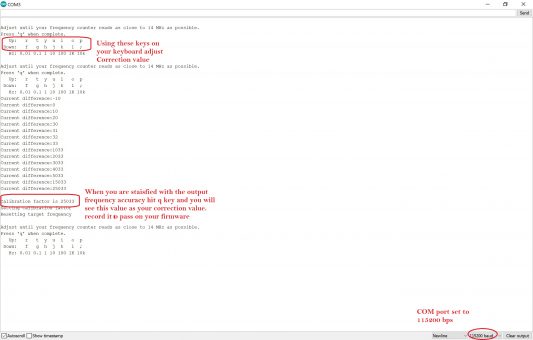
Choose your COM port accordingly in serial monitor and set it to 115200 bps. When you run you will see this screen shot. Using the keys displayed on the screen on your keyboard and your si5351 output connected to your scope or frequency counter try to match the frequency as exact as 14000000 Hz.
When you are satisfied with the frequency accuracy hit the q button on the keyboard and record the calibration factor on a piece of paper!
Now we have the calibration factor we can load the HF RX software into our Arduino IDE.
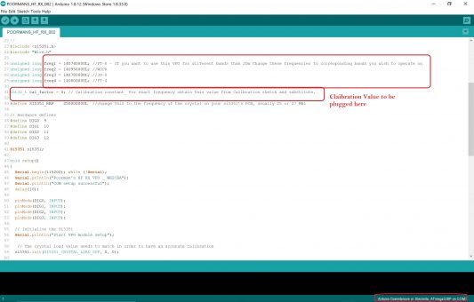
When you load the POORMANS_HF_RX_002.ino to your Arduino IDE from the attached zip folder you will see this screenshot.
Now we need to plug in the calibration factor to the location I pointed out with a red rectangle instead of zero.
Now we are ready to program the Arduino. Hit the upload button and hopefully all goes well and you are done!
Now if you choose FT-8 which is DIP 1 is ON and the rest is in OFF position, measure the frequency to verify all is good and running. Your scope or frequency counter should show 14074000 Mhz. Try all the other DIP position accordingly to make sure all is working good.
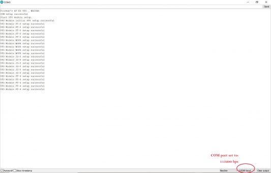
You can also Verify your selections and to check if the Arduino is running the program by serial monitor set to 115200 bps. You will see a screenshot like this:
To make a quick check if the receiver is working you can use an earphone and plug it into the audio socket of the receiver and increase the audio level to suit by the 10k trimpot.
You should hear a low steady sound. Then connect to a 20 m/14mhz antenna and choose DIP 1/FT-8. Try to listen changing alternating tones. If you hear them then congratulations you just received FT-8!
Now to use your HF receiver in action depending on your mode, download and install on your computer WSJT/X for FT-8, WSPR or FT-4 and JS8Call for JS-8. The links for these programs are listed above.
Connect audio output of the receiver to your soundcard MIC input with a suitable 3.5 mm to 3.5 mm jack audio adapter cable.
Weak Signal Modes are depending on an accurate timing which means that your computer clock must be accurate to 1 second. To achieve this download and install a program called Dimesion4:
http://www.thinkman.com/dimension4/
When you run dimesion4 it synchronizes your PC clock with an NTP server atomic clock. This will solve the accuracy problem of your PC clock sync.
You can check how accurate your PC time is from this site:
https://time.is/
it is always a good idea to check how accurate your clock is before running WSJT/X or JS8Call for a successful RX.
Now you can run the program, let’s say WSJT/X and from settings of WSJT/X enter your callsign. Then go to audio and set your audio card settings. Then go to reporter setting and check enable pskreporter spotting.
From modes choose FT-8 and set DIP switch, DIP1 to ON. Rest to OFF.
If you are connected to an antenna and if your receiver passed previous headphone audio test then you should start to see a green vertical line labeled as db move up and down. Try to hold that line at maximum 50 db by adjusting the 10k audio level trimpot. If it hits red than the signal is overloading the mic input.
Now you should be able to see a screen filling with amateur radio station call signs like this:
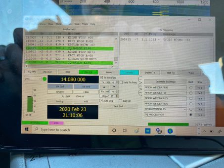
This is a screen shot for FT-4 but FT-8 is similar to this.
To check which stations you received and how far they are:
www.pskreporter.info
What else can be improved?
– This is a barebones simple receiver. It can be improved with a band pass filter at the input of SA602 and may be with a crystal filter? This is certainly beyond me!
– A variable tuning digital vfo can be programmed with Arduino and SI5351 to use this receiver to listen the whole band coverage.
– As I mentioned other frequencies and bands can be plugged in to be able to work on different bands. For example FT-8 on all available bands selectable by DIP switch, DIP 1 20 m, DIP2 40 m, DIP 3 80 m and DIP 4 160 m FT_8 receiving. You have to switch the low pass filters accordingly!
– Can be used as a cheap stand alone WSPR beacon reporting receiver with a raspberry PI.
I hope you find this receiver useful and fun to experiment with.
73’s
Barbaros Asuroglu, WB2CBA, NY

