TI SR10 Calculator Clone with Claude
ti-duino-sr-10
Cloning a Texas Instruments SR-10, Early 1970’s Scientific Calculator with the help of VIBE Coding and my friend CLAUDE!
Texas Instruments SR-10 was a basic scientific calculator back from 1970’s.
http://www.datamath.org/Sci/WEDGE/SR-10-BK.htm
It wasn’t anything fancy or special when compared to todays sophisticated Calculators. Though it has a special place in my memories and in my heart!
I started my education in METU – Middle East Technical University in Ankara/Turkey in 1980! Yes, I am a relic! :).
in 1980’s Turkey a scientific calculator was a luxury. My humble first year passed with Slide rule and basic 4 operand calculator!
In the beginning of my second year, my father gifted me a Texas Instruments SR-10 where SR stands for Slide Rule Calculator, Grand father of modern scientific calculators. I loved it!
I used SR-10 in my second year in college with great joy coming from a painful year of Slide rule and nonscientific calc. Then I jumped to Hewlett Packard HP41-CV which was a giant leap.
Anyway, that TI SR-10 had a special place after my college education in my professional life. I used it in various construction sites and projects I worked in well into 2000s. Then it got stolen from my desk in 2004 at work!
That TI SR-10 never left my memories.
Late August of this year I was searching for a ESP32 LED dot matrix Display on EBAY and I came across a BUBBLE type LED 12digit display on sale for 14.95$! The same type of display that was in TI SR-10! With an impulse buy I got it! 😊
The display arrived and I tested to see if it is in working order and sure it was in great shape and all segments of all digits working!
So, the work began to create a clone of TEXAS INSTRUMENTS SR-10 with new tech. I used ATMEGA328P-AU to use Arduino IDE environment for ease of programming.
I started with the schematic of TI SR-10 Clone, Here is my SR-10 clone schematic:
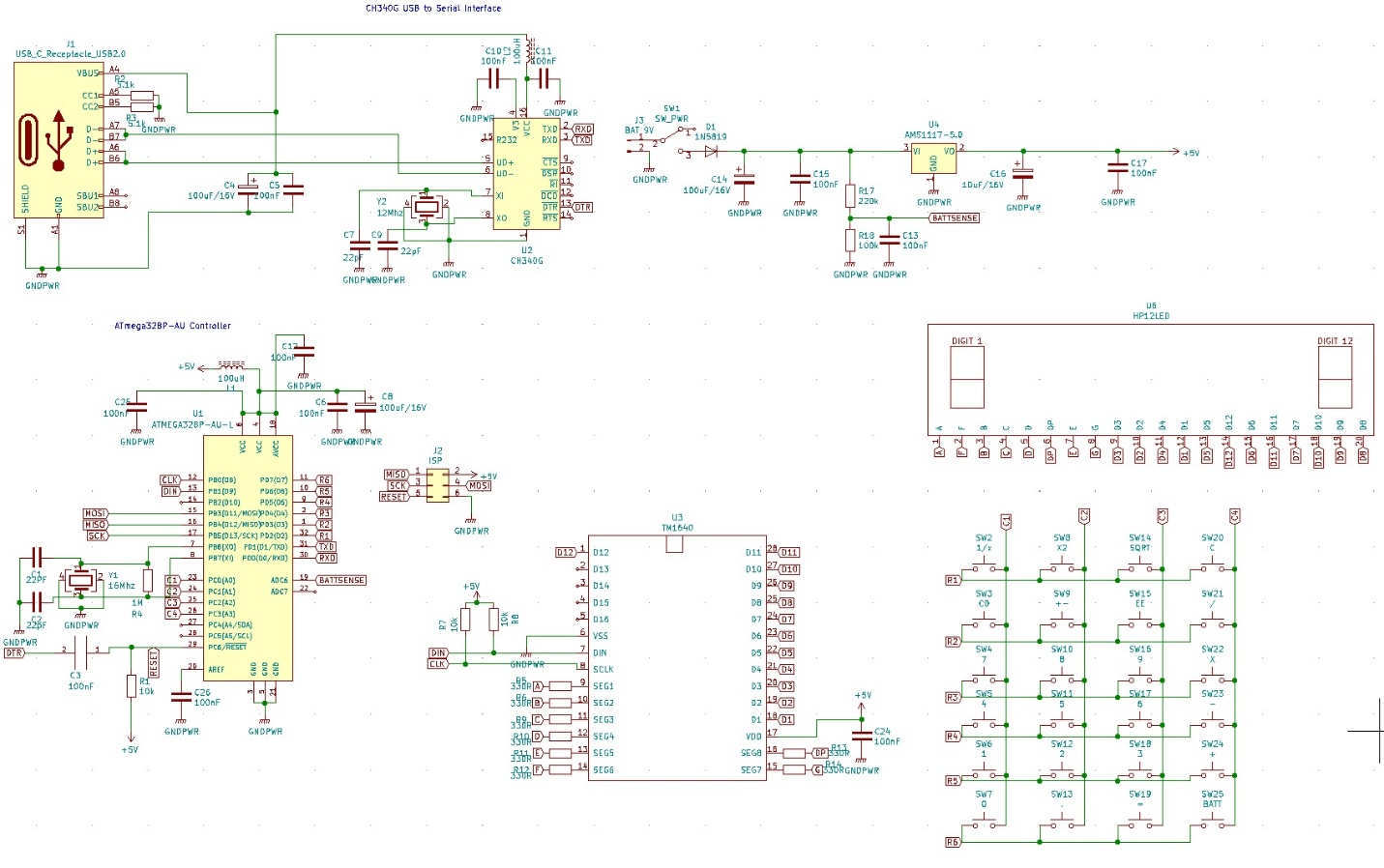
I used Chinese TM1640, 16 Digit 7 segment led driver. It is cheap and readily available. For 24 key keyboard I chose 6 by 4 matrix. Original SR-10 has 23 keys and in my keyboard 1 key to spare which I used it to check battery level.
I used KICAD PCB software for the SR-10 Calculator PCB. Settled on the same dimension of original SR10 and the layout of display/power switch and keyboard to give the same feel of SR-10 when holding. I decided to use first a 9V PP3 battery but then opted for 6 X AA battery. The main aim is to power with 9V, same as the original TI SR-10. I also added a USB to TTL converter for ease of programming. The USB Converter is powered from USB so it doesn’t draw any current from Battery when not in use.
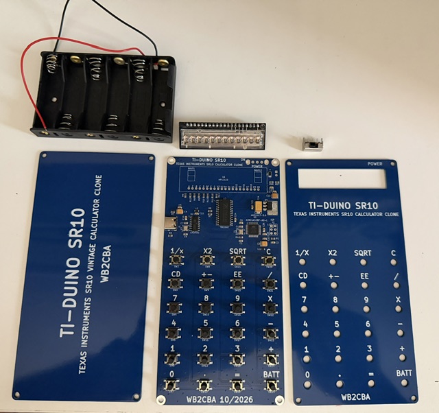
I used top and back PCB panels on purpose rather than a 3D case to show the internals of my clone TI-SR-10.
I decided to design with full SMT components to make it look clean and more pro-like. The details of TI-SR-10 Calculator Clone project is in my Github page in this link including fabrication files and SR10 clone test firmware and SR-10 Calculator arduino Firmware:
https://github.com/WB2CBA/TI-DUINO-SR-10-VINTAGE-CALCULATOR-CLONE
Here are photos of Calculator PCBs and assembled SR-10 Calculator Clone.
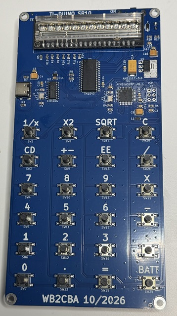
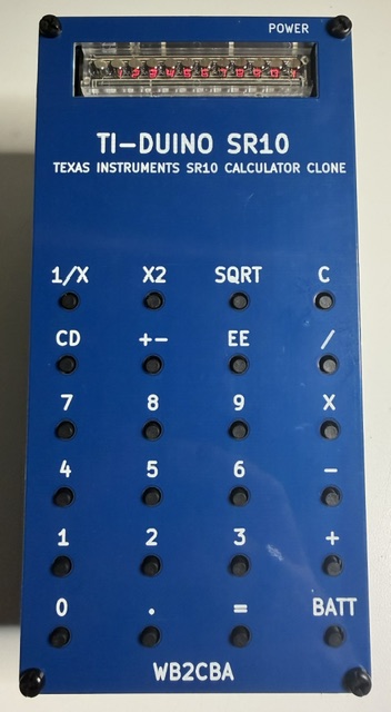
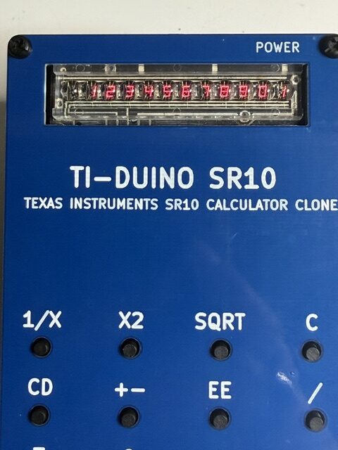
After finishing building my Clone SR-10 I powered up to see if it will pass smoke test and it passed with flying colors!
Now I needed to test the hardware if all is in working order. As a first step I uploaded Arduino Uno bootloader. Then I started to work on an Arduino test sketch. After making some progress on test code I gave up and decided that this project is a good one for VIBE Coding and for my dear friend Claude Code to handle! 😊
So, I started to chat with Claude! Below you can read my full exchange with Claude and our process of developing a working TI-SR-10 Clone Calculator Firmware.
My asks are in plain text and Claude’s replies are in BOLD text. I also distinguished by placing Barb and Claude in front of each conversation start line.
Barb – This is my TEXAS INSTRUMENTS SR10 Vintage LED CALCULATOR PROJECT- (I Uploaded Calculator schematic at this point) This is the schematic of my SR-10 Vintage Calculator project with vintage 7 segment bubble12 digit led display. I am using Arduino ide and Arduino uno board as simulated board for this project. Can you create a sketch to test led digits and keyboard matrix as per the schematic I uploaded. i want to verify if the circuit board is working properly
(Claude starts thinking and evaluating process for 2.5 minutes and comes up with a test sketch, then explains it to me)
CLAUDE – I’ve written calculator_board_test.ino, which tests the 12-digit display and the key matrix on your board. I checked it on my computer against a simulated TM1640 and keypad, but I haven’t run it on the real board or compiled it for the ATmega.
Setup
- Put the file in a folder named calculator_board_test, choose Board = Arduino Uno, and open the Serial Monitor at 115200 baud.
- The slide switch must be ON with the 9V battery connected, both for uploading and for testing. USB only powers the CH340, not the 5V rail.
What it does, in order
- Keyboard wiring check: it reports any row or column shorted to GND, any row/row or column/column bridge, and any key already reading as pressed at power-up.
- Display test:
- All segments and decimal points on for 2 seconds.
- Each segment A to DP lit on every digit in turn.
- A single “8.” walked across D1 to D12.
- 0 to 9 on every digit.
- A brightness ramp, then “HELLO” and “1234567890.12”.
- Key test: pressing a key print something like KEY SW10 R3 C2 label: 8 on the Serial Monitor and shows r3 c2 16-24 on the LED display (the last number is how many of the 24 keys have been seen). When all 24 have been pressed once, it shows PASS. The BATT key shows the battery voltage.
Serial commands
- d repeats the display test.
- r resets the key count.
- + and – change brightness.
- v prints the battery voltage.
Pin mapping I read from your schematic
- TM1640 CLK is D8 and DIN is D9.
- Rows R1 to R6 are D2 to D7, and columns C1 to C4 are A0 to A3.
- The battery sense line is read with analogRead(6).
Things to know
- Digit order: if D1 turns out to be the right-most digit on your display, set REVERSE_DIGITS to true near the top. It only affects the text, not the hardware tests.
- Display wiring: the TM1640 can’t report back whether it is connected, so the display tests have to be checked by eye. A dark segment during the segment walk points to that segment’s resistor or trace. A dark digit during the digit walk points to that digit’s grid line.
- Ghost keys: the matrix has no diodes, so three or more keys held together can show ghost presses. The sketch prints a note when that happens.
- Battery reading: it assumes about 0.35V lost across D1. Adjust DIODE_DROP if it disagrees with a multimeter.
( I upload sketch to SR-10 Clone and test the hardware)
Barb – perfect! all displays and keys passed with flying colors! thank you (You need to be polite with an AI! You’ll never know what will happen in the future!)
CLAUDE – Glad the board checked out. The TM1640 driver, the font and the key scan in that sketch are reusable, so they can go straight into the calculator firmware.
If you want to keep going, the next step could be the SR-10 calculation logic (entry, operators, 1/x, X2, SQRT, EE, +-, CD, C) on the 12-digit display. Just tell me when you’re ready.
Barb – I am ready for SR-10 calculator Clone to be alive and running. go ahead with the calculator sketch please
(Claude starts it’s thinking/processing/evaluating process for 3.5 minutes this time before replying)
Time to build the SR-10 firmware. A plain float on the ATmega only gives about 7 digits, so I’ll write a proper 13-digit decimal (BCD) math core. That way 1÷3×3 gives exactly 1 and 0.1+0.2 gives exactly 0.3. I’ll test the math against Python’s decimal library before you load it.
The sketch is written. Now the test harness: it feeds numbers and key sequences directly into the sketch’s functions, so I can compare against Python’s decimal arithmetic.
The calculator sketch is ready as sr10_calculator.ino. I tested it only in a simulation on my computer and haven’t compiled it for the ATmega, so it’s untested on your board.
To load it, save the file in a folder named sr10_calculator, use the same settings as the board test (Uno, CH340 port, slide switch ON), and upload. The display shows “Sr-10” briefly, then 0.
Keys
- Digits and .: enter a number, up to 11 digits.
- + – X / and =: chain calculation, like the real SR-10 with no operator priority, so 2 + 3 X 4 = gives 20.
- 1/x, X2, SQRT: apply instantly to the number on the display.
- +-: changes the sign, or the exponent’s sign after EE.
- EE: starts an exponent, so 1.5 EE 3 is 1500 and 2 EE +- 4 is 0.0002.
- C: clears everything, including “Error”.
- CD: clears only the number being typed and keeps the pending operation.
- BATT: shows the battery voltage for 2 seconds.
How it calculates. An ordinary float on this chip is only good for about 7 digits, so I wrote 13-digit decimal arithmetic. 1/3 X 3 gives exactly 1, 0.1 + 0.2 gives exactly 0.3, and SQRT of a perfect square is exact. The display shows 11 digits. In the simulation, 5,524 random add, subtract, multiply, divide and square-root cases matched Python’s decimal library exactly. Scripted key sequences (chains, errors, EE, CD, clear) and the full keypad-to-display path also gave the expected results.
Display behavior
- Numbers that need more than 11 digits, or tiny numbers with many digits, switch to scientific notation (8-digit mantissa on the left, exponent on the right), for example 1.2345679 11. Short small numbers like 0.000125 stay plain.
- Division by zero, SQRT of a negative number, or a result beyond 10^99 shows Error until you press C.
- The minus sign sits right next to the number. If you’d rather have it at the far left, tell me.
- The Serial Monitor (115200 baud) mirrors the display text. Set DEBUG_SERIAL to false near the top to turn that off.
If you hit any compile errors or odd behavior on the real board, send me the message and I’ll fix it.
(Claude posts the SR-10_Calculator.ino sketch here which I download for testing)
Barb – I’ll upload and test now.
CLAUDE – If you find anything odd in the display layout or the key behavior, tell me what you pressed and what you saw. Next steps could be a repeat-= constant mode (if you change your mind), a different minus-sign position, or low-battery warning.
Barb – I upload and ran SR-10_Calculator.ino sketch and it runs as exactly how SR-10 works. great job!
CLAUDE – Thank you, glad it feels like the real SR-10. Enjoy the build, and come back anytime if you want tweaks or find anything odd while testing.
The whole conversion with Claude to build the testing and working SR-10 calculator firmware took me around 20 minutes from start to finish! Incredibly efficient process. If I wanted to code this firmware for this calculator project it can easily take me a week with all the searching and steep know how to match TI SR-10 calculation quirks and debugging etc.
I appreciate much VIBE coding and AI coding help. Makes life easier on my hobby project coding and saves a lot of head scratching time!
I am actively using my SR-10 Calculator Clone at my work nowadays and many heads are turning to ask what the heck is that! 😊 My memories with my old and faithful TI SR-10 are alive in this TI SR-10 Calculator Clone.
Barb, WB2CBA, October, 2026