uSDX – An Arduino Based SDR All Mode HF Transceiver – PCB Iteration V1.02
uSDX – An Arduino based, DIY, QRP, SDR, All mode HF Transceiver – PCB Iteration V1.02
uSDX is an Arduino based SDR all mode HF QRP transceiver project brain child of Guido PE1NNZ. I took Guido’s brilliant design and devised couple versions of PCB’s to build it.
The history of uSDX and details of version 1.00 and 1.01 pcb is here:
https://antrak.org.tr/blog/usdx-a-compact-sota-ssb-sdr-transceiver-with-arduino/
So what is this article all about if we have two versions of PCB of the same project! Well version 1.00 PCB was a test pcb to see if I can design a HF PCB and to see if everything is working as planned. It didn’t! There were couple of mistakes on my part and lessons learned and corrected.
So the corrected version of PCB is V1.01. So it worked great and no errors? Nope! I messed up again! It was an improvement over V1.00 but had two glitches and that’s why there is a modification section for V1.01. Also thanks to brilliant members of UCX forum we found out that we shouldn’t let FST3253 pin number 1 floating as it effects receive characteristics badly.
As there was also positive suggestions from fellow hams who built and tested V.1.01 pcb to improve some of the features of both pcb versions. This made me to think of a new version of my PCB series which gave birth to V1.02.
Corrections of version 1.01:
– Correction 1 – FST3253 pin 1 tied to VCC pin 16.
– Correction 2 – Floating pins of 74ACT00 tied to a logic level which is VCC.
– Correction 3 – 10 nF cap forgotten is added to TX PA line between RX switch BS170 to improve TX which was left out on PCB V1.01 and had to be corrected by modification.
All these glitches of V1.01 are now corrected and tested on V1.02 and they are working.
The Improvements and additions to V1.02:
– Multiband capability with dedicated band LPF module:
In V1.00 and V1.01 I used QRP LABS Low Pass Filters as they are excellent, good quality and I never thought of multiband capability so much as I was mainly working on 20 m due to my restrictive antenna space. This meant that L/C TX band specific PA combination before the LPF was fixed on the pcb. The PA L/C pair is band dependent and if you optimize for other bands this pair has to be changed too with LPF. I was thinking first to switch the whole PA with 3 x BS170 + L/C PA pair +LPF by carrying all to a separate pcb module. But this seemed impractical as there was no need to duplicate 3xBS170 for every band. Then I entertained to create a band select LPF pcb with relays for every band and control circuitry to strap underneath the TRX pcb. This seemed too cumbersome for a simplistic KISS(Keep It So Simple) approach.
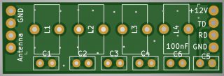
At the end I settled on carrying band specific PA L/C pair with 7 pole LPF filter on a small enough pluggable module slightly bigger than QRP LABS LPF filter. This way band optimized pluggable modules for each band can be built and changed in the field with ease. A Poorman’s Multiband capability!
– LM1117 – 5.0V Regulator
A new and better 5 Volts regulator was needed desperately to replace good old LM7805 in these modern times.
– SI5351 Smd vs SI5351 Module Option:
I got many requests from fellow hams to replace SI5351 Module with SMD SI5351 option. So I decided to do it but at the same time I wanted to keep the option of SI5351 Module as smd SI5351 is not so easy to solder in place. Now we have both options for SI5351, either smd SI5351 or your choice of SI5351 Modified module. Also that horrible detail of soldering headers to connect to SI5351 Module SMA output pins are gone! You just solder the module with headers on one side and that’s it. What was I thinking when I designed previous versions!!!
The smd version of SI5351 uses 27 mhz crystal which makes the pcb compatible with Guido’s firmware without any change.
– DC Barrel type Power Jack:
I added a DC Barrel type Connector power input jack which I think will make life easier than that two pin header DC power input. I still kept the two pin header as this pcb is compatible with the power backpack pcb I released in this article:
https://antrak.org.tr/blog/usdx-sdr-ssb-sota-transceiver-battery-pack/ and this is a good power connection point for that backpack pcb.
– Handheld Microphone/Speaker input jack:
Thanks to Ken Delap KX9U’s suggestion to include a microphone/speaker jack to use a cheap handheld microphone/speaker combination in the field. BAOFENG UV-3R handheld transceivers use a 4 pole 3.5 mm jack for handheld MIC/SPK and their handheld MIC/SPK’s are dirt cheap. This 3.5 mm jack is compatible with those cheap handheld microphone/speakers.
– Here is a link for such speaker/mic handheld unit:
https://www.amazon.com/Speaker-Baofeng-Remote-Microphone-Handheld/dp/B015PWT3L4
– BNC vs SMA antenna Connector Choice:
I received many requests for BNC type antenna connector and I understand SMA is not the most rugged connection point. Being a VHF/UHF guy I always prefer SMA, though I agree on HF and in the field BNC has a better chance of survival. So thanks to Kees, K5BCQ’s brilliant suggestion to burry a SMA footprint into the BNC footprint, now one of them can be used depending on your choice.
– Face and Bottom Plate PCB’s:
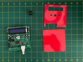
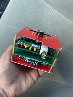
A cheap and proper enclosure is what I struggled when I built my uSDX pcbs. I used to sandwich them between a spare PCB at the bottom and a plastic cover on the top cutting the lcd area and drilling for the controls etc. which is pain in the back! So I thought why not design a dedicated top and bottom plate pcb and sandwich the whole trx with couple of spacers between these pcb plates. And that’s what I did!
– Miguel Angelo Bartie PY2OHH’s Power Amplifier Modification:
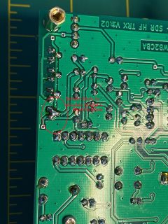
Miguel placed a BS170 between power amplifier and 3 x BS170’s. I included this modification in this version of pcb for experimenters to experiment with. This can be eliminated by shorting out all pins of that extra Q5 BS170 and de-soldering or not installing R28. More on this later…
– Test Points :
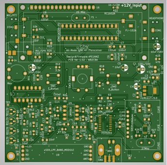
I’ve added 6 Test points to make measurements easy on crucial points of the pcb. Test points can be spotted on the schematic.
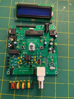
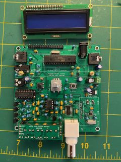
Here is PCB V1.02:
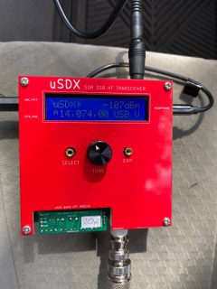
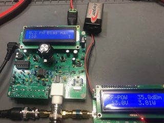
Ken Delap, KX9U’s PCB V1.02 Build in transmit test:
Building PCB V1.02:
Building PCB V1.02 is similar to PCB V1.01. All the parts used and build info are similar to PCB V1.01 and so is the testing and firmware upload etc.
This link will help on the build:
https://antrak.org.tr/blog/usdx-a-compact-sota-ssb-sdr-transceiver-with-arduino/
So what is different? Some of the parts are additions to V1.01 and some of them are different. Here is a list of parts that are different than V1.01 parts and links where to find them:
LM 1117-5.0 Regulator:
CUI 43514 3.5 mm 4 pole MIC/SPK Connector:
https://www.digikey.com/product-detail/en/cui-devices/SJ-43514-SMT-TR/CP-43514SJCT-ND/669734
DC Barrel Type Connector:
https://www.digikey.com/product-detail/en/cui-devices/PJ-102A/CP-102A-ND/275425
BNC Antenna Connector:
https://www.digikey.com/product-detail/en/amphenol-rf/031-5431-10RFX/ARF1690-ND/2041816
Rotary Encoder:
Any 5 pole switch type rotary encoder will work on PCB V1.02 but there is a catch. If you wish to use the face plate then the rotary encoder shaft should be a long one meaning more than or equal to 25 mm so that it can extend over the face plate. Here is a link for such a long shaft rotary encoder from bourns:
https://www.digikey.com/products/en?keywords=pec11l-4125f-s0020
Multi Band LPF Module:
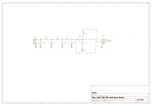
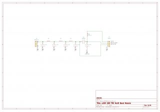
Multiband module pcb is a pluggable band specific module that incorporates both the PA L/C pair and the 7 pole LPF. This way customized band modules can be build for each band we wish to operate uSDX on.
For each band a customized band module is needed meaning that all PA L/C pair values and LPF L/C values are calculated for that band we want to operate on. These pluggable modules for the desired band is switched to operate on a specific band before turning on the TRX. It is like vintage WW2 transceivers where the crystals were plugged for the operating frequency selected.
Here are the values of multi band module components for each band:
80m Band:
L1-T37-2 / 25 turns
L2-T37-2 / 27 turns
L3- T37-2/27 turns
L4- T37-2/24 turns
C1-470pf
C2-1200pf
C3- 1200pf
C4-470pf
C5-180pf
60m Band:
L1-T37-2 / 23 turns
L2-T37-2 / 24 turns
L3- T37-2/23 turns
L4- T37-2/24 turns
C1-680pf
C2-1200pf
C3- 1200pf
C4-680pf
C5-30pf + 56pf in parallel
40m Band:
L1-T37-6 / 21 turns
L2-T37-6 / 24 turns
L3- T37-6/21 turns
L4- T37-2/16 turns
C1-270pf
C2-680pf
C3- 680pf
C4-270pf
C5-56pf
30m Band:
L1-T37-6 / 19 turns
L2-T37-6 / 20 turns
L3- T37-6/19 turns
L4- T37-2/14 turns
C1-270pf
C2-560pf
C3- 560pf
C4-270pf
C5-30pf
20m Band:
L1-T37-6 / 16 turns
L2-T37-6 / 17 turns
L3- T37-6/16 turns
L4- T37-2/10 turns
C1-180pf
C2-390pf
C3- 390pf
C4-180pf
C5-30pf
17m Band:
L1-T37-6 / 13 turns
L2-T37-6 / 15 turns
L3- T37-6/13 turns
L4- T37-2/9 turns
C1-100pf
C2-270pf
C3- 270pf
C4-100pf
C5-30pf
These are the values of components that are on the multiband modules for each band.
I copied these values from QRP Labs QCX manual Rev5:
https://www.qrp-labs.com/images/qcx/assembly_A4-Rev-5e.pdf
GQRP Low Pass Filter is a very useful guide on designing Low pass filters also.
Here is a link for GQRP Low Pass Filter PDF:
https://www.qrp-labs.com/images/lpfkit/gqrplpf.pdf
Some of the band toroid turn values are slightly different than QCX ones. Low Pass Filters are open to experimenting.
Beware that I tested only 20m band values. I didn’t test the other band component values so I can’t verify if these values will work for those bands other than 20m.
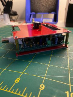
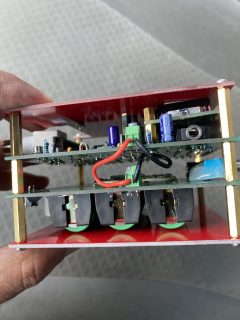
Band module is installed up side down as in the photos. This is on purpose to keep the profile low so that inductors doesn’t stick out above the face plate profile to block installation of face plate flush with LCD.
Be careful to correctly orient and install band module as both sides have 4 pin headers! Wrong installation may damage PA BS170 mosfets!
Face Plate and Bottom Plate:
Face and bottom plates are to sandwich pcb V1.02 to create a protective enclosure. Metric 3 spacers can be used to bolt the plates to pcb.
PCB V1.02 is compatible with uSDX battery backpack and can be sandwiched in between in this version too.
https://antrak.org.tr/blog/usdx-sdr-ssb-sota-transceiver-battery-pack/
Miguel Angelo Bartie, PY2OHH Power Amplifier modification:
Miguel published a modification for TX power amplifier.
Here is the link for Miguel’s modification thread in UCX IO groups and Miguel’s blog on uSDX with his modified schematic for reference.
Link to Miguel’s mod UCX IOgroups threads:
https://groups.io/g/ucx/message/1449
https://groups.io/g/ucx/topic/75763824#1549
Link to Miguel’s blog:
https://www.qsl.net/py2ohh/trx/usdx/usdx.html
I included this modification in the schematics and pcb of V1.02. The fourth BS170, Q5 is this additional mosfet at the PA input. Also R28 is the pull down Resistor.
– If the original schematic of Guido is preferred without this modification similar to PCB V1.01:
– Do not install Q5.
– Solder a blob to short all 3 pins of Q5 as in the photo
– Do not solder R28
that’s it. Now the PA is compliant with Guido’s original schematic, ucx.png.
– If you wish to experiment with Miguel’s mod:
– Solder Q5 in place
– Solder R28 in place
And Miguel’s mod is active. Beware that Miguel’s mod needs higher PA Bias min and PA Bias max values.
Conclusion:
I hope V1.02 is up to the challenge of SOTA fields and will find many adopters among QRP hamradio operators. I thank again Guido PE1NNZ for his great design and software skills and also I would like to thank Ken Delap, KX9U for his courage to build PCB V1.02 even before I could build and test my V1.02 (due to heavy work load and no time) and carrying out all tests to verify that it is working as expected.
All gerber files, schematic files, firmwares and KiCAD files are included at the bottom of this article. I will release KiCAD files here after some cleaning and refinement when I can find some time to sit down.
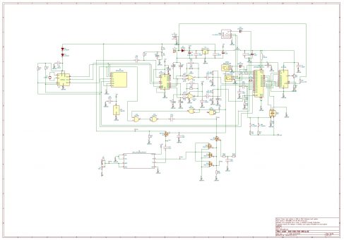
uSDX V1.02 Schematic
uSDX Multiband Module Schematic
uSDX V1.02 Gerber Files
uSDX_V1.02i hotfix applied firmwares for WB2CBA PCB V1.01 and V1.02
KiCAD Files
A Fancy Case For uSDX
Bob Benedict, KD8CGH has designed and printed a good looking case.
Barbaros Asuroglu aka Barb
WB2CBA, NY, 08/12/2020
– This pcb design can not be used commercially without the consent of Barbaros Asuroglu WB2CBA.

